Sensor Circuit
MANUAL_CONTROL_FOR_HEATER
Published:2009/6/24 3:53:00 Author:Jessie | From:SeekIC

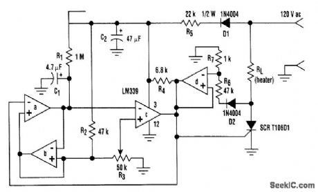
Built around an LM339 quad comparator, this circuit provides manual control of the output of a resistive heater or other load with a long time constant. The circuit's design uses minimal parts, thus it's inexpensive, and generates very low RFI.Comparators a,b, and c form a low-frequency pulse-width modulator. Sections a and b form a sawtooth oscillator (of approximately 0.25 Hz), with capacitor C1 being charged through RI and dis-charged through section a's open collector output. R2 and R3 set the upper voltage limit for the saw-tooth wave. The hysteresis means that C1 is discharged to nearly 0V, creating a voltage swing that is identical to the adjustment range of R3.Comparator c, in conjunction with potentiometer R3, converts the sawtooth wave form to a vari-able duty-cycle drive for the silicon-controlled rectifier.Increasing voltage at R3's wiper means increasing the on time. Section d holds the SCR gate low if the line voltage is above approximately 3.5 V, preventing turn on at mid-cycle and ensuring low RFI.The oscillator frequency is roughly determined by 1/0.7R1C1 Resistance R1 must be greater than 4R2 or the oscillator will lock up. ReducingR1 will increase the lower voltage limit of the sawtooth; in-creasing it might cause lock-up.
Reprinted Url Of This Article:
http://www.seekic.com/circuit_diagram/Sensor_Circuit/MANUAL_CONTROL_FOR_HEATER.html
Print this Page | Comments | Reading(3)

Article Categories
power supply circuit
Amplifier Circuit
Basic Circuit
LED and Light Circuit
Sensor Circuit
Signal Processing
Electrical Equipment Circuit
Control Circuit
Remote Control Circuit
A/D-D/A Converter Circuit
Audio Circuit
Measuring and Test Circuit
Communication Circuit
Computer-Related Circuit
555 Circuit
Automotive Circuit
Repairing Circuit
Code: