Sensor Circuit
IONIZATION_CHAMBER_SENSOR
Published:2009/7/5 22:25:00 Author:May | From:SeekIC

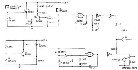
MOSFET Q1 with high input impedance monitors voltage level at divider formed by R1 and ionization chamber, with output of Q1 going to Q2 which forms other half of differential amplifier. With smoke Ievel of 2% orhigher, Q3 is tumed on and applies logic 1 to one input of NAND gate 1 in asymmetrical astable MVBR Capacitor in MVBR charges quickly and discharges slowly, making alarm hom sound during discharge via inverter 3 and driver transistor Q4 Comparator circuit Q5 drives second MVBR to energize hom through inverter 6 and same driver Q4 when battery is low, but with distinctive 1-s toot every 23 s to conserve energy remaining in battery and differentiate from fire waming.-A.Pshaenich and R. Janikowski, Gas and Smoke Detector Uses Low-Leakage MOS Transistor, Electronics, Nov. 28, 1974, p 124-125.
Reprinted Url Of This Article:
http://www.seekic.com/circuit_diagram/Sensor_Circuit/IONIZATION_CHAMBER_SENSOR.html
Print this Page | Comments | Reading(3)

Article Categories
power supply circuit
Amplifier Circuit
Basic Circuit
LED and Light Circuit
Sensor Circuit
Signal Processing
Electrical Equipment Circuit
Control Circuit
Remote Control Circuit
A/D-D/A Converter Circuit
Audio Circuit
Measuring and Test Circuit
Communication Circuit
Computer-Related Circuit
555 Circuit
Automotive Circuit
Repairing Circuit
Code: