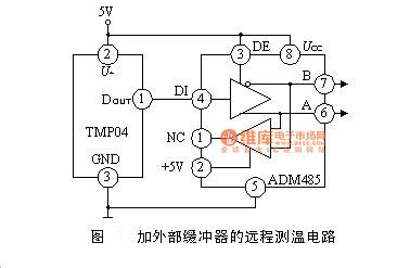
Position: Home > Circuit Diagram > Sensor Circuit > External buffer remote temperature measurement circuit diagram
Sensor Circuit
External buffer remote temperature measurement circuit diagram
Published:2014/3/25 21:31:00 Author:lynne | Keyword: External buffer remote temperature measurement circuit diagram, | From:SeekIC

After the microcontroller coupled TMP03/04 easily microcomputer were measured in a counter t1, t2, then the software calculates the temperature. Because TMP03/04 is time ratio (t1/t2) to measure the temperature, so the computer does not require a very precise frequency counting, but counting frequency should be high enough.
Reprinted Url Of This Article:
http://www.seekic.com/circuit_diagram/Sensor_Circuit/External_buffer_remote_temperature_measurement_circuit_diagram.html
Print this Page | Comments | Reading(3)

Article Categories
power supply circuit
Amplifier Circuit
Basic Circuit
LED and Light Circuit
Sensor Circuit
Signal Processing
Electrical Equipment Circuit
Control Circuit
Remote Control Circuit
A/D-D/A Converter Circuit
Audio Circuit
Measuring and Test Circuit
Communication Circuit
Computer-Related Circuit
555 Circuit
Automotive Circuit
Repairing Circuit
Code: