Sensor Circuit
ELECTRONIF_THERMOSTAT
Published:2009/6/22 23:16:00 Author:Jessie | From:SeekIC

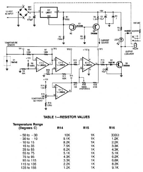
A diode, such as a IN4148, has a typical -2m V/℃ temperature coefficient at a 1 mA diode cur-rent. Q1 and Q2 form a constant current source. D1 is the temperature sensor. IC1-a and -b are dc amplifiers, with IC1-c a temperature reference voltage supply. IC1-d is a comparator with variable hysteresis. R14, R15, and R16 are chosen depending on the thermostat range desired. Q3 is a relay driver (2N3904). The relay used should handle the Ioad current or an optoisolator triac combination can be used.
Reprinted Url Of This Article:
http://www.seekic.com/circuit_diagram/Sensor_Circuit/ELECTRONIF_THERMOSTAT.html
Print this Page | Comments | Reading(3)

Article Categories
power supply circuit
Amplifier Circuit
Basic Circuit
LED and Light Circuit
Sensor Circuit
Signal Processing
Electrical Equipment Circuit
Control Circuit
Remote Control Circuit
A/D-D/A Converter Circuit
Audio Circuit
Measuring and Test Circuit
Communication Circuit
Computer-Related Circuit
555 Circuit
Automotive Circuit
Repairing Circuit
Code: