Sensor Circuit
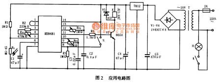
Doppler effect sensor RD9481 application circuit diagram
Published:2014/3/24 21:32:00 Author:lynne | Keyword: Doppler effect sensor RD9481 application circuit diagram, RD9481 | From:SeekIC

>Application Circuit
>RD9481R typical application circuit shown in Figure 2, the circuit is auto-sensing circuit lights, daytime lights are not bright, not bright at night when no one around, lights turn on automatically when someone walking.
After mains 220V transformer transformer, rectifier by (V1 ~ V4), the filter capacitor C4 and the voltage regulator circuit 7812 to get the DC supply voltage. RG photosensitive resistor R1 connected in series with the power supply voltage, the voltage divider circuit composed. During the day light shines onto the photosensitive resistor RG, RG showed low resistance, RD9481 5 feet low, blocking the trigger signal, the circuit does not work; night RG was high resistance, RD9481 5 feet high, so that the circuit to work . S is working mode selection switch, S is closed as a duplicate trigger work, S open to non-repeatable trigger work. Adjusting RP1, the sensitivity of the circuit can be adjusted to change the detection range can be adjusted to change the output high RP2 delay time adjustment block RP3 can change the timer has expired.
Reprinted Url Of This Article:
http://www.seekic.com/circuit_diagram/Sensor_Circuit/Doppler_effect_sensor_RD9481_application_circuit_diagram.html
Print this Page | Comments | Reading(3)

Article Categories
power supply circuit
Amplifier Circuit
Basic Circuit
LED and Light Circuit
Sensor Circuit
Signal Processing
Electrical Equipment Circuit
Control Circuit
Remote Control Circuit
A/D-D/A Converter Circuit
Audio Circuit
Measuring and Test Circuit
Communication Circuit
Computer-Related Circuit
555 Circuit
Automotive Circuit
Repairing Circuit
Code: