Sensor Circuit
Digit Counter Circuit
Published:2011/5/11 5:00:00 Author:chopper | Keyword: Digit Counter | From:SeekIC

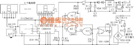
As shown in figure,the original mechanical counterjust has two magnetic switch signals terminals, while electronic counter increases input terminal c,d of AC6.3V,and thereare 4 binding posts. C1,C2,VD1,VD2 form voltage-multiplying circuit,filter circuit,and output 5V stable DC voltage after voltage stabilization,and become about 3.6V DC voltage after voltage reduction by VD3,VD4.E1 is a small Ni-cd rechargeable battery.When the mains supply is available,the supply will charge E1;and when the supply stops,E1 will charge the load to maintain the value of the counter.VD3 and VD4 here have an effect of insulation. When input magnetic switch at the both end of a,b closes,the AC 220V voltage is connected.The voltage will be converted into AC pulsating voltage after it is reduced by R1~R4 and bridgedioded by VD5~VD8.And the AC pulsating voltage provides luminotron of the photo-coupler with voltage after it is limited by R5 to make luminotron glow. The resistance of photosensitive tube will decrease because of light and generate a decline pulse,which will reverse direction through N3.And the pulse offers power to trigger of N1,N2 and N1 will output count pulse. N1,N2,N3 constitute pulse shaping circuit together.
Reprinted Url Of This Article:
http://www.seekic.com/circuit_diagram/Sensor_Circuit/Digit_Counter_Circuit.html
Print this Page | Comments | Reading(3)

Article Categories
power supply circuit
Amplifier Circuit
Basic Circuit
LED and Light Circuit
Sensor Circuit
Signal Processing
Electrical Equipment Circuit
Control Circuit
Remote Control Circuit
A/D-D/A Converter Circuit
Audio Circuit
Measuring and Test Circuit
Communication Circuit
Computer-Related Circuit
555 Circuit
Automotive Circuit
Repairing Circuit
Code: