Sensor Circuit
DIODE_SENSOR_FOR_LASERS
Published:2009/7/8 23:25:00 Author:May | From:SeekIC


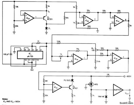
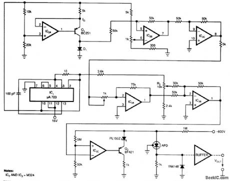
Laser-receiver circuits must bias their avalanche photo diodes (APD) to achieve optimal gain. Unfor-tunately, an APD's gain depends on the operating temperature. The circuit controls the operating voltage of an APD over a large temperature range to maintain the gain at the optimal value. The circuit uses D1 as a temperature sensor, thermally matched with the APD.A voltage regulator, IC1, supplies the necessary reference voltage to the circuit. IC2A and Q1 bias D1 at a constant current. IC2B, IC2C, IC3A/IC3B, and IC3C amplify D1's varying voltage and set Q2 to he optimal-gain corresponding value. Potentiometer RI controls the amplification over a range of 5 to 5. R2 controls the voltage level, which corresponds to the optimal gain of the APD at 22°C (the erature is specific to the type of APD). The circuit shown was tested with an RCA C 30954E APD. The tests cov-ered -40 to +70°C and used a semiconductor laser. The laser radiation was transmuted on the APD's active surface in the climatic room via fiberoptic cable. The gain varied by, at most, 10.2 dB over the entire temperature range.
Reprinted Url Of This Article:
http://www.seekic.com/circuit_diagram/Sensor_Circuit/DIODE_SENSOR_FOR_LASERS.html
Print this Page | Comments | Reading(3)

Article Categories
power supply circuit
Amplifier Circuit
Basic Circuit
LED and Light Circuit
Sensor Circuit
Signal Processing
Electrical Equipment Circuit
Control Circuit
Remote Control Circuit
A/D-D/A Converter Circuit
Audio Circuit
Measuring and Test Circuit
Communication Circuit
Computer-Related Circuit
555 Circuit
Automotive Circuit
Repairing Circuit
Code: