Remote Control Circuit
Wireless remote control switch circuit 5
Published:2011/5/8 21:53:00 Author:Rebekka | Keyword: Wireless remote control switch | From:SeekIC


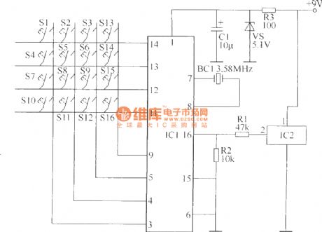
Wireless remote control transmitter circuit is composed of control buttons S1 ~ S16, resistors R1 ~ R3, capacitor C1 regulator diode VS, crystal oscillator BC1, DTMF encoder IC IC1 and IC2 wireless remote control transmitter integrated circuit components. It is shown as above.
Components selectionR1, R2 and R4, R6 ~ R39 use 1/4W carbon film resistors or metal film resistors; R3 and R5 use 1/2W metal film resistors. C1 ~ C3 use 16V voltage aluminum electrolytic capacitors. VS uses 1/2W, 5.1V voltage regulator diode silicon. VL1 ~ VL16 use φ3mm common light-emitting diodes.V1 uses S9013 type silicon NPN transistor; V2 ~ V17 use C8050 or S8050, 3DG8050 silicon NPN transistor. IC1 uses UM95087 type phone with a selection of DTMF dialing code integrated circuits; IC2 uses HS101 type wireless remote control transmitter thick-film integrated circuits; IC3 uses HS201 type wireless remote control receiver thick film integrated circuit; IC4 uses MC145436 type telephone with DTMF decoder integrated circuits; IC5 uses CD4514 or MC14514 type 4-16 line decoder IC; IC6 ~ IC13 (D1 ~ D16) use CD4013 dual D flip-flop integrated circuits.
Reprinted Url Of This Article:
http://www.seekic.com/circuit_diagram/Remote_Control_Circuit/Wireless_remote_control_switch_circuit_5.html
Print this Page | Comments | Reading(3)

Article Categories
power supply circuit
Amplifier Circuit
Basic Circuit
LED and Light Circuit
Sensor Circuit
Signal Processing
Electrical Equipment Circuit
Control Circuit
Remote Control Circuit
A/D-D/A Converter Circuit
Audio Circuit
Measuring and Test Circuit
Communication Circuit
Computer-Related Circuit
555 Circuit
Automotive Circuit
Repairing Circuit
Code: