Remote Control Circuit
Wireless remote control switch circuit 4
Published:2011/5/8 22:05:00 Author:Rebekka | Keyword: Wireless remote control switch | From:SeekIC


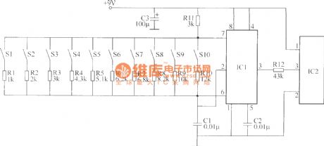
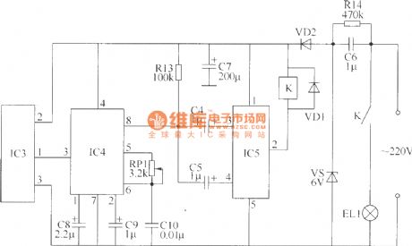
The wireless remote control switch circuit is composed of the wireless remote control transmitter circuitry and wireless remote control receiver control circuit. Wireless remote control transmitter circuit is composed of the controlled variable frequency oscillator and a wireless remote control transmitter circuit. It is shown as above.
Component selectionR1 ~ R14 use 1/4W carbon film resistors or metal film resistors. RP1 uses WSW type organic solid fine resistors. C1, C2 and C10 use monolithic capacitors; C3 ~ C5 and C8, C9 use aluminum electrolytic capacitor voltage 16V; C7 uses electrolytic capacitors voltage 25V; C6 uses 400V voltage polyester capacitor or CBB capacitors. VD1 and VD2 use 1N4007 type silicon rectifier diode.VS uses 1W, 6.2V silicon voltage regulator diodes. IC1 uses NE555 type base integrated circuit; IC2 uses TDC1808 type wireless remote control transmitter IC module; IC3 uses TDC1809 type wireless remote control receiver IC module; IC4 uses LM567 type audio PLL decoder IC; IC5 uses DM21 type dual steady-state driver IC module. K uses 6V DC relay. S1 ~ S10 use moving micro-Hop (open) button.
Reprinted Url Of This Article:
http://www.seekic.com/circuit_diagram/Remote_Control_Circuit/Wireless_remote_control_switch_circuit_4.html
Print this Page | Comments | Reading(3)

Article Categories
power supply circuit
Amplifier Circuit
Basic Circuit
LED and Light Circuit
Sensor Circuit
Signal Processing
Electrical Equipment Circuit
Control Circuit
Remote Control Circuit
A/D-D/A Converter Circuit
Audio Circuit
Measuring and Test Circuit
Communication Circuit
Computer-Related Circuit
555 Circuit
Automotive Circuit
Repairing Circuit
Code: