Remote Control Circuit
Wireless remote control plus and minus resistor network circuit diagram
Published:2011/10/19 22:15:00 Author:Rebekka | Keyword: Wireless remote control plus , minus resistor network | From:SeekIC
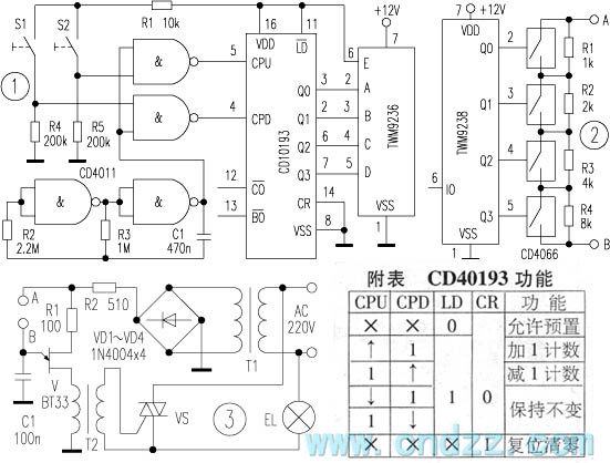
Transmitter circuit is shown in figure 1. CD40193 is a dual clock synchronous 4-bit binary up / down counter, andits function is shown as the table. CPU is the addition clock impulse input terminal, and CPD is a subtraction input of the clock pulse. When it inputs 0 to 15 pulses, its output terminals Q3 ~ Q0 change with the oder of 0000 ~ 1111 (addition) or 1111 ~ 0000 (subtraction). It is fired by the built-in antenna outside. CD4011 NAND chip is composed of two ultra-low frequency oscillators. The other two NAND gatesare the addition and subtraction counting gate. When the subtraction S1 door is open, CD40193 reduces the count. When the addition count door S2 is open, CD40193 starts the additional counts. The working voltage of CD4011 and CD40193 is 5V. Ultra-low frequency oscillator frequency is about 0.5 ~ 2Hz.
Reprinted Url Of This Article:
http://www.seekic.com/circuit_diagram/Remote_Control_Circuit/Wireless_remote_control_plus_and_minus_resistor_network_circuit_diagram.html
Print this Page | Comments | Reading(3)

Article Categories
power supply circuit
Amplifier Circuit
Basic Circuit
LED and Light Circuit
Sensor Circuit
Signal Processing
Electrical Equipment Circuit
Control Circuit
Remote Control Circuit
A/D-D/A Converter Circuit
Audio Circuit
Measuring and Test Circuit
Communication Circuit
Computer-Related Circuit
555 Circuit
Automotive Circuit
Repairing Circuit
Code: