Remote Control Circuit
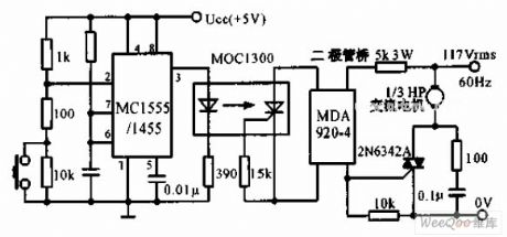
The switch shut off time delay circuit diagram
Published:2011/5/8 7:10:00 Author:Rebekka | Keyword: The switch shut off time delay | From:SeekIC

The switch shut off time delay circuit is shown as below. The switch shut off time delay circuit is composed of the timer, optocouplers, bridge SCR, SCR AC switch. When the control button is released, the keeping motor or other AC start power for 1 hour. Button closure. 2 pin voltage step-down Ucc / 3 below. The output pin 3 rises. LED lights. The bridge SCR AC switch TRIAC triggers the motor to run. The 7 feet of the capacitor began to charge at the same time. When the voltage rises to 2Ucc / 3 and the timer output decreases, the motor stops running.
Reprinted Url Of This Article:
http://www.seekic.com/circuit_diagram/Remote_Control_Circuit/The_switch_shut_off_time_delay_circuit_diagram.html
Print this Page | Comments | Reading(3)

Article Categories
power supply circuit
Amplifier Circuit
Basic Circuit
LED and Light Circuit
Sensor Circuit
Signal Processing
Electrical Equipment Circuit
Control Circuit
Remote Control Circuit
A/D-D/A Converter Circuit
Audio Circuit
Measuring and Test Circuit
Communication Circuit
Computer-Related Circuit
555 Circuit
Automotive Circuit
Repairing Circuit
Code: