Remote Control Circuit
The reporting timing contact printer circuit
Published:2011/8/15 22:15:00 Author: | Keyword: contact printer | From:SeekIC

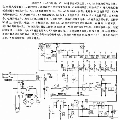
In the circuit, A1 and A2 are the timers; A3 and A4 are the second signal generators; A5 and A6 are the sound signal generator. At the input terminal of A1, the R and C time delay net is connected there, by changing the value of R, the time constants of R and C are changed, i.e the time of A1 input terminal LEV rising from low to transfer potential is changed. The oscillating frequency of A3 and A4 is 1Hz, the frequency of A5 and A6 is 1000Hz or so. In the circuit, K1 is the power supply switch; k2 is the in-out converting switch; K3 is the focus switch; K4 is the jogging switch; K6 is the 10*10 selecting switch.
Reprinted Url Of This Article:
http://www.seekic.com/circuit_diagram/Remote_Control_Circuit/The_reporting_timing_contact_printer_circuit.html
Print this Page | Comments | Reading(3)

Article Categories
power supply circuit
Amplifier Circuit
Basic Circuit
LED and Light Circuit
Sensor Circuit
Signal Processing
Electrical Equipment Circuit
Control Circuit
Remote Control Circuit
A/D-D/A Converter Circuit
Audio Circuit
Measuring and Test Circuit
Communication Circuit
Computer-Related Circuit
555 Circuit
Automotive Circuit
Repairing Circuit
Code: