Remote Control Circuit
Remote control robot circuit
Published:2011/8/26 2:50:00 Author:TaoXi | Keyword: Remote control, robot | From:SeekIC


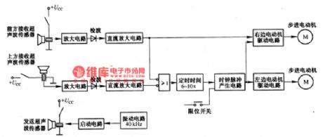
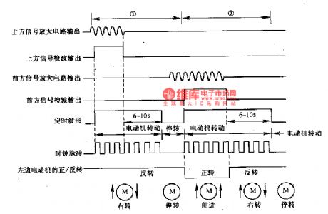
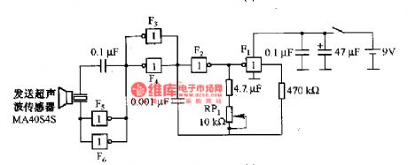
The remote control robot circuit is as shown in the figure. The figure 2-36(a) is the circuit diagram, the figure 2-36(b) is the operating timing diagram. The rotation process of the rebot is: in the circuit, the ultrasonic launching circuit is composed of the 40kHz oscillating circuit and driving circuit. The two sensors receive the ultrasonic wave: one receiving sensor is installed in the upper part of the robot; another receiving sensor is installed in front of the rebot.
In region 1, the ultrasonic sensor receives the ultrasonic wave signal and the signal is amplified by the amplifier circuit, then it is detected by the diode, at last it changes into the logic level to drive the timing circuit.
Reprinted Url Of This Article:
http://www.seekic.com/circuit_diagram/Remote_Control_Circuit/Remote_control_robot_circuit.html
Print this Page | Comments | Reading(3)

Article Categories
power supply circuit
Amplifier Circuit
Basic Circuit
LED and Light Circuit
Sensor Circuit
Signal Processing
Electrical Equipment Circuit
Control Circuit
Remote Control Circuit
A/D-D/A Converter Circuit
Audio Circuit
Measuring and Test Circuit
Communication Circuit
Computer-Related Circuit
555 Circuit
Automotive Circuit
Repairing Circuit
Code: