Remote Control Circuit
Multi-functional infrared remote controller 555, MC1558
Published:2011/9/4 20:45:00 Author:TaoXi | Keyword: Multi-functional, infrared, remote controller | From:SeekIC

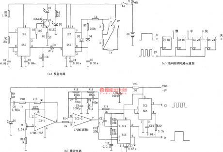
The multi-functional infrared remote controller is as shown in the figure. This circuit is composed of the infrared pulse launch circuit and the infrared receiving circuit. The infrared transmitter is as shown in figure (a), it is composed of two multivibrators which use the time-base circuit 555 as the core. The oscillation frequency of the multivibrator which is composed of the IC1(555) and R1, R2, C1 is f=1.44/(R1+2R2)C1, the corresponding frequency of the parameters in the figure is about 3kHz, the signal can be used to drive the carrier wave of the infrared emission diode D1. Another multivibrator is composed of the IC2(555), C5, R7 and the resistor which is connected with the switch K2, it can be used in the keying coding application. The output pulse waveform adds to the pin-4 of IC1 that can be used as the keying modulation signal.
Reprinted Url Of This Article:
http://www.seekic.com/circuit_diagram/Remote_Control_Circuit/Multi_functional_infrared_remote_controller_555_MC1558.html
Print this Page | Comments | Reading(3)

Article Categories
power supply circuit
Amplifier Circuit
Basic Circuit
LED and Light Circuit
Sensor Circuit
Signal Processing
Electrical Equipment Circuit
Control Circuit
Remote Control Circuit
A/D-D/A Converter Circuit
Audio Circuit
Measuring and Test Circuit
Communication Circuit
Computer-Related Circuit
555 Circuit
Automotive Circuit
Repairing Circuit
Code: