Remote Control Circuit
INTERFACE_CIRCUITS_FOR_THE_REMOTE_CONTROL_TRANSMITTER
Published:2009/6/17 22:55:00 Author:May | From:SeekIC

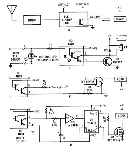
Shown here are several possible interface circuits that can be used with the remote-control transmitter. The one in A illustrates a typical FM stereo MUX decoder with a load connected directly to the open-collector output of a TA7343 PLL. The circuit in B illustrates an optoisolator-coupler out-put driving a 12-V relay coil via a general-purpose transistor. C shows the gate of an N-channel power MOSFET connected to the output of a 4N33. The final circuit, D, is a toggle flip-flop that allows push-on/push-off control.
Reprinted Url Of This Article:
http://www.seekic.com/circuit_diagram/Remote_Control_Circuit/INTERFACE_CIRCUITS_FOR_THE_REMOTE_CONTROL_TRANSMITTER.html
Print this Page | Comments | Reading(3)

Article Categories
power supply circuit
Amplifier Circuit
Basic Circuit
LED and Light Circuit
Sensor Circuit
Signal Processing
Electrical Equipment Circuit
Control Circuit
Remote Control Circuit
A/D-D/A Converter Circuit
Audio Circuit
Measuring and Test Circuit
Communication Circuit
Computer-Related Circuit
555 Circuit
Automotive Circuit
Repairing Circuit
Code: