Remote Control Circuit
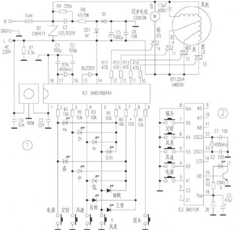
Fusibo deluxe remote control landing fan circuit diagram
Published:2011/10/19 21:01:00 Author:Rebekka | Keyword: Fusibo, deluxe remote control, landing fan | From:SeekIC

Figure 1 is the receiving board control circuit diagram, because it uses ventilator specific IC BA8206BA4K, and it has the functions of infrared receive amplifier, decoding, timed control, LED driver, therefore it has the simple structure without debugging, which is safe and convenient, and it is easy self-restraint, so it is possible to use in transforming traditional machinery velocity modulation ventilator. 220V city electricity is limited and bucked by FUSE, C7, R8, R9, rectified by D1, voltage stabilized by ZD1, filtered by C5, C6, then it forms 5V DC voltage to provides power for the IC1 {14} foot and infrared receiver.
Reprinted Url Of This Article:
http://www.seekic.com/circuit_diagram/Remote_Control_Circuit/Fusibo_deluxe_remote_control_landing_fan_circuit_diagram.html
Print this Page | Comments | Reading(3)

Article Categories
power supply circuit
Amplifier Circuit
Basic Circuit
LED and Light Circuit
Sensor Circuit
Signal Processing
Electrical Equipment Circuit
Control Circuit
Remote Control Circuit
A/D-D/A Converter Circuit
Audio Circuit
Measuring and Test Circuit
Communication Circuit
Computer-Related Circuit
555 Circuit
Automotive Circuit
Repairing Circuit
Code: