Remote Control Circuit
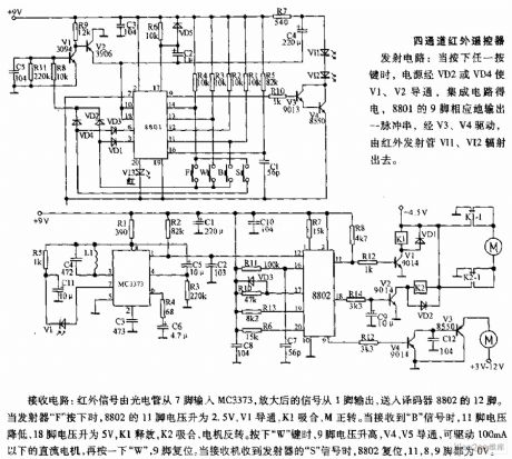
Four channels infrared remote controller circuit diagram
Published:2011/8/11 5:57:00 Author:nelly | Keyword: Four channels, infrared remote controller | From:SeekIC

The receiving circuit: the infrared signal is inputed to MC3373 from 7 foot by phototube, the amplified signal outputs from 1 foot, it is transported into the 12 foot of decoder 8802. When the transmitter F is pressed, the voltage of 8802's 11 foot up to 2.5V, V1 turns on, K1 pulls in, M is forward rotation. When it receives B signal, 11 foot's voltage drops, 18 foot's voltage up to 5V, K1 releases, K2 pulls in, the motor is reversal rotation. Pressing W , 9 foot's voltage rises, V4, V5 turn on, it can drive the DC motors which under 100mA, pressing W again, 9 foot resets. When the receiver receives the transmitter's S signal, 8802 resets, 8, 9 feet are all 0V.
Reprinted Url Of This Article:
http://www.seekic.com/circuit_diagram/Remote_Control_Circuit/Four_channels_infrared_remote_controller_circuit_diagram.html
Print this Page | Comments | Reading(3)

Article Categories
power supply circuit
Amplifier Circuit
Basic Circuit
LED and Light Circuit
Sensor Circuit
Signal Processing
Electrical Equipment Circuit
Control Circuit
Remote Control Circuit
A/D-D/A Converter Circuit
Audio Circuit
Measuring and Test Circuit
Communication Circuit
Computer-Related Circuit
555 Circuit
Automotive Circuit
Repairing Circuit
Code: