Remote Control Circuit
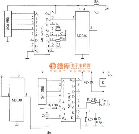
Digital code remote control switch circuit diagram
Published:2011/5/9 1:12:00 Author:Rebekka | Keyword: Digital code remote control switch | From:SeekIC

Digital code remote control switch circuit composed of digital codec MC145026/MC145027 andtiny radio transceivers M303S/M303R is shown as above.
Press the transmitter button SA, the circuit start to work. The serial encoded signal outputs from MC145026 to 15 feet, passes the transmitter module M303S and shoots out. The receiver module M303R of receiving circuit receives the encoded signals and sends to the decoder MC145027. When the address code of the encoder and decoder are exactly the same, the decoding of MC145027 effectively instructs a high-side output pulse signal. The transistor VT turns on, the drive relay pulls in. The switch control function will be completed.
Reprinted Url Of This Article:
http://www.seekic.com/circuit_diagram/Remote_Control_Circuit/Digital_code_remote_control_switch_circuit_diagram.html
Print this Page | Comments | Reading(3)

Article Categories
power supply circuit
Amplifier Circuit
Basic Circuit
LED and Light Circuit
Sensor Circuit
Signal Processing
Electrical Equipment Circuit
Control Circuit
Remote Control Circuit
A/D-D/A Converter Circuit
Audio Circuit
Measuring and Test Circuit
Communication Circuit
Computer-Related Circuit
555 Circuit
Automotive Circuit
Repairing Circuit
Code: