Remote Control Circuit
Additional simple TV remote control circuit (LM555, CD4017)
Published:2011/8/26 1:45:00 Author:TaoXi | Keyword: Additional, simple, TV, remote control | From:SeekIC

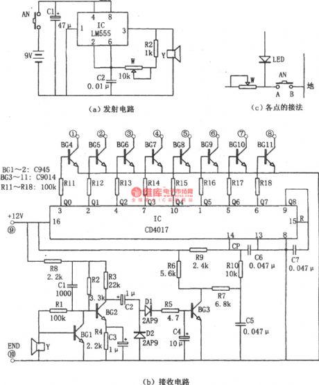
The additional simple TV remote control circuit is as shown in the figure. This circuit is composed of the launch circuit and the receiving circuit. The core of the launch circuit is the astable multivibrator which is composed of the time-base circuit 555 and the R2, W, C2, the oscillation frequency is decided by the R2, W, C2. The receiving circuit is composed of the amplification, rectification, counter circuit. The IC(CD4017) is the decimal counter/pulse distributor. The pin-9 outputs the Q8 and adds it to the pin-15 of the reset port. The CD4017 will output the Q0~Q7 which have the high level.
Reprinted Url Of This Article:
http://www.seekic.com/circuit_diagram/Remote_Control_Circuit/Additional_simple_TV_remote_control_circuit_LM555_CD4017.html
Print this Page | Comments | Reading(3)

Article Categories
power supply circuit
Amplifier Circuit
Basic Circuit
LED and Light Circuit
Sensor Circuit
Signal Processing
Electrical Equipment Circuit
Control Circuit
Remote Control Circuit
A/D-D/A Converter Circuit
Audio Circuit
Measuring and Test Circuit
Communication Circuit
Computer-Related Circuit
555 Circuit
Automotive Circuit
Repairing Circuit
Code: