Remote Control Circuit
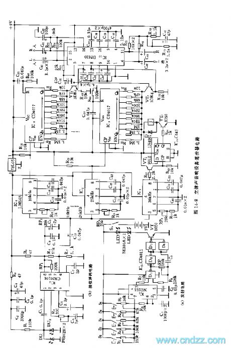
555 stereo audio equipment remote controller circuit
Published:2011/6/15 18:55:00 Author:TaoXi | Keyword: 555, stereo, audio equipment, remote controller | From:SeekIC

As the figure 14-8 shows, the remote controller is composed of the infrared ray coding emitter and the infrared ray decoding receiver. Figure (a) shows the 5-channel infrared coding emitter circuit. The astable multivibrator is composed of the 555 and C1, R6, R1 ~ R5, the oscillation frequency f=1.44/(R1-5+2R6)C1, the five channels are 10kHz,15kHz,20kHz,25kHz and 30kHz. The IC2 is the quad 2-input port NAND gate, the controlled oscillator is composed of the D1 and D2, the oscillation frequency f0=1/(1.4~2.2)RP1C3, f0 of the figure is about 38 to 40kHz. The infrared ray transmitting tube uses the SE303A or the HG4100 series tube. The receiver decoding circuit is composed of the infrared receiver tube, the special decoding circuit, the 5-channel single-tone decoder, the counting circuit and the stereo control circuit.etc.
Reprinted Url Of This Article:
http://www.seekic.com/circuit_diagram/Remote_Control_Circuit/555_stereo_audio_equipment_remote_controller_circuit.html
Print this Page | Comments | Reading(3)

Article Categories
power supply circuit
Amplifier Circuit
Basic Circuit
LED and Light Circuit
Sensor Circuit
Signal Processing
Electrical Equipment Circuit
Control Circuit
Remote Control Circuit
A/D-D/A Converter Circuit
Audio Circuit
Measuring and Test Circuit
Communication Circuit
Computer-Related Circuit
555 Circuit
Automotive Circuit
Repairing Circuit
Code: