© 2008-2012 SeekIC.com Corp.All Rights Reserved.
power supply circuit
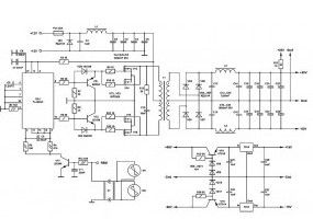
± 60 Volt Switching Power Supply for PA
Published:2013/3/22 2:44:00 Author:Ecco | Keyword: ± 60 Volt , Switching Power Supply, PA | From:SeekIC

The main part of any amplifier is the power supply. It is clear that to obtain a high output 12-volt battery is not enough. Therefore, we must first create a voltage converter, which enables a bipolar supply +-60V with a capacity of no less than 400W. Digging on the forum found a fairly simple and relatively good scheme.
The brain of this converter is a chip TL494NC, it creates pulses of a given frequency. Frequency set elements R1 and C8. Then these pulses hit the transistors VT1, VT2, which are the control keys for the output transistors. Alternately opening, the output transistors in the primary winding creates an alternating current of high frequency. The transformer increases the voltage to 60V specified, then the current is rectified by a diode bridge. Inductors and capacitors smooth the ripple and high frequency interference. The transformer is wound on a ferrite ring glued two rings size 45 * 28 * 8 marks NM2000. All faces of the ring rounding a file, then wrapped a rag trance tape.
Reprinted Url Of This Article:
http://www.seekic.com/circuit_diagram/Power_Supply_Circuit/±_60_Volt_Switching_Power_Supply_for_PA.html
Print this Page | Comments | Reading(3)

Article Categories
power supply circuit
Amplifier Circuit
Basic Circuit
LED and Light Circuit
Sensor Circuit
Signal Processing
Electrical Equipment Circuit
Control Circuit
Remote Control Circuit
A/D-D/A Converter Circuit
Audio Circuit
Measuring and Test Circuit
Communication Circuit
Computer-Related Circuit
555 Circuit
Automotive Circuit
Repairing Circuit
New published articles
Response in 12 hours

Code: