
power supply circuit
Index 282
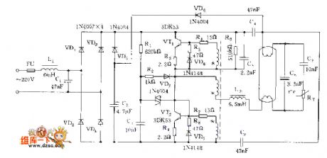
Mini Switch Power Charger Circuit Diagram
Published:2011/3/21 1:49:00 Author:Rebrecca | Keyword: Mini Switch, Power Charger

The Mini Switch Power Charger Circuit Diagram is shown as below.
(View)
View full Circuit Diagram | Comments | Reading(1060)
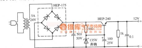
12V simple regulators circuit diagram two
Published:2011/3/21 1:49:00 Author:Rebrecca | Keyword: simple regulators
12V simple regulators circuit diagramtwo is shown as below.
(View)
View full Circuit Diagram | Comments | Reading(609)
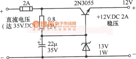
12V simple regulators circuit diagram one
Published:2011/3/21 1:49:00 Author:Rebrecca | Keyword: simple regulators
12V simple regulators circuit diagram one is shown as below.
(View)
View full Circuit Diagram | Comments | Reading(542)
12V Series and parallel compound fixed power supply circuit diagram
Published:2011/3/21 1:49:00 Author:Rebrecca | Keyword: Series and parallel compound, fixed power supply
View full Circuit Diagram | Comments | Reading(922)
MC34063 2.2V-6V Boost to 7V circuit diagram
Published:2011/3/21 1:47:00 Author:Rebrecca | Keyword: Boost to 7V
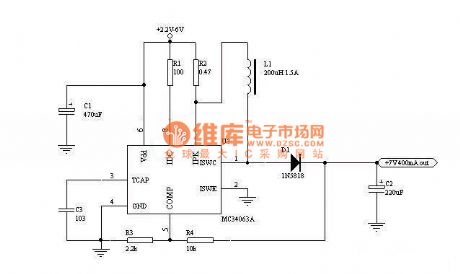
MC34063 2.2V-6V Boost to 7V circuit diagram is shown as below.
(View)
View full Circuit Diagram | Comments | Reading(3967)
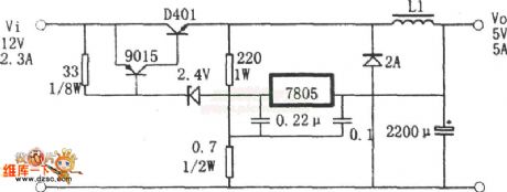
12V Soft start fixed voltage power supply circuit diagram
Published:2011/3/21 22:48:00 Author:Rebekka | Keyword: Soft start, fixed voltage power supply

View full Circuit Diagram | Comments | Reading(1234)
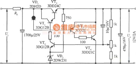
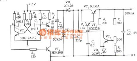
Switching regulator supply circuit diagram with three terminal regulator
Published:2011/3/29 3:26:00 Author:Ecco | Keyword: three terminal regulator, Switching regulator supply

As shown in chart, the switching regulator supply circuit is made from three terminal regulator, and the working principle can be understood by the equivalent circuit diagram. For some reason, the output voltage V0 declined slightly, its separate pressure V3 in R5 and R6 fall subsequently, and magnified by VT3, the Ic3 decreases, and Ic2 increases, namely the current flowed through R1 and VD1 increases, V1 drops, V4, Ic1 increase, V2 rises, and cause V3 down... This process is a positive feedback chain reaction, and the last result is that VT1, VT2 are conducted strongly, VT3 stops working, IC1 charges for L1, C1, and Vo rises, then causes a series of positive feedback chain reaction. After a short time, Vo's rising results in the conduction of VT3, the deadline of VT1, VT2. The current stored on L1 released by load and diode VD2, which resulting in V4 dropping to 0. Of course Vo also slowly down until the second flip, namely completes self-excited oscillation of a cycle. The whole circuit works in the cycle of switching state.
(View)
View full Circuit Diagram | Comments | Reading(702)
Efficient Sine Inverter Circuit Diagram
Published:2011/3/21 1:47:00 Author:Rebrecca | Keyword: Sine Inverter

Efficient Sine Inverter Circuit Diagram is shown as below.
(View)
View full Circuit Diagram | Comments | Reading(1087)
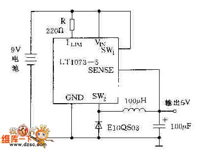
Step-down circuit diagram composed of LT1073
Published:2011/3/28 4:18:00 Author:Nicole | Keyword: Step-down
View full Circuit Diagram | Comments | Reading(889)
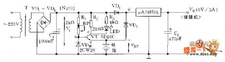
Automatic protection DC Power Supply circuit diagram preventing PC power-down
Published:2011/3/28 3:43:00 Author:Nicole | Keyword: DC Power Supply
View full Circuit Diagram | Comments | Reading(537)
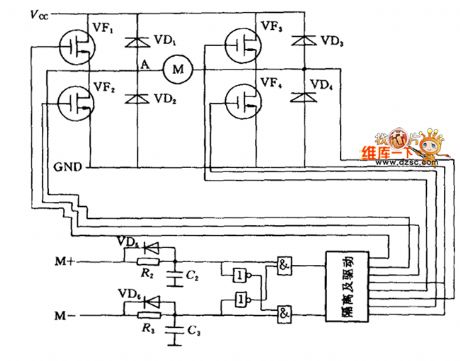
DC motor bridge drive circuit diagram
Published:2011/3/28 4:05:00 Author:Nicole | Keyword: DC motor, bridge drive
View full Circuit Diagram | Comments | Reading(639)
Low-cost and high power submultiple electronic rectifier circuit diagram
Published:2011/3/28 4:13:00 Author:Nicole | Keyword: electronic rectifier, submultiple
View full Circuit Diagram | Comments | Reading(683)
Practical electronic rectifier circuit diagram
Published:2011/3/28 4:13:00 Author:Nicole | Keyword: electronic rectifier

View full Circuit Diagram | Comments | Reading(635)
Turning +15V power supply into -5V power supply fixed voltage power supply circuit diagram
Published:2011/3/22 4:27:00 Author:Rebekka | Keyword: fixed voltage power supply
View full Circuit Diagram | Comments | Reading(628)
±15V Tracking Regulator Power Supply Circuit Diagram 2
Published:2011/3/22 4:32:00 Author:Rebekka | Keyword: Tracking Regulator
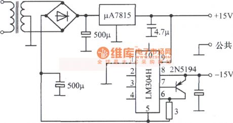
±15V Tracking Regulator Power Supply Circuit Diagram2 is shown as below.
(View)
View full Circuit Diagram | Comments | Reading(597)
Neon high pressure power supply circuit
Published:2011/3/25 0:32:00 Author:Joan | Keyword: Neon, power supply , high pressure

View full Circuit Diagram | Comments | Reading(1047)
High input - high output integrated voltage regulator circuit 3
Published:2011/3/24 23:06:00 Author:Joan | Keyword: High input , high output , integrated voltage regulator
View full Circuit Diagram | Comments | Reading(614)
LM317 adaptive adjustable regulated voltage supply circuit diagram
Published:2011/3/28 22:55:00 Author:Ecco | Keyword: regulated voltage supply

The power supply is LM317 regulated voltage components, which is use in adaptive circuitry. According to the output voltage , the circuitry will change the input voltage automatically to reduce the differential pressure between the input and output. And that can reduce the power cost of the power supply itself. Among them, VD5, VW, VT2 R5, R6, C10 and relay K constitute of adaptive switching action circuit, when output voltage Vo is lower than 14V, Vw will be stopped as lacking of breakdown voltage and no current pass it, VT2, K stop and K-1 is in closed state, the 14 V secondary voltage of transformer alternating current access regulated voltage circuitry. Or, when the output voltage is higher than 14V, VW is brokendown, VT2 is conducted. K gets electron, and K-1 moves to make 280V ac voltage access circuitry. Ensuring the differential pressure between the input and output does not exceed 15V. The output of the circuitry is continuously adjustable in 1.25 ~ 30V, and the maximum current is 3A.
(View)
View full Circuit Diagram | Comments | Reading(3772)
Logic input level remote-controlled integration fixed voltage power supply circuit diagram
Published:2011/3/22 22:05:00 Author:Rebekka | Keyword: Logic input , level remote-controlled integration , fixed voltage power supply
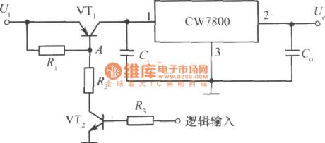
Logic input level remote-controlled integration fixed voltage power supply circuit diagram is shown as below.
(View)
View full Circuit Diagram | Comments | Reading(554)
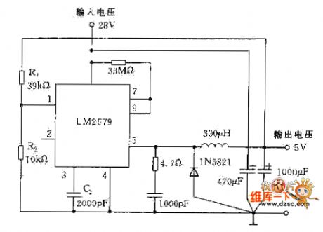
Step-down regulator circuit diagram composed of LM2579
Published:2011/3/28 4:34:00 Author:Nicole | Keyword: step-down regulator
View full Circuit Diagram | Comments | Reading(906)
| Pages:282/291 At 20281282283284285286287288289290291 |
Circuit Categories
power supply circuit
Amplifier Circuit
Basic Circuit
LED and Light Circuit
Sensor Circuit
Signal Processing
Electrical Equipment Circuit
Control Circuit
Remote Control Circuit
A/D-D/A Converter Circuit
Audio Circuit
Measuring and Test Circuit
Communication Circuit
Computer-Related Circuit
555 Circuit
Automotive Circuit
Repairing Circuit