power supply circuit
Width modulation, frequency modulation hybrid type switching power supply (2)
Published:2011/7/12 1:34:00 Author:TaoXi | Keyword: Width modulation, frequency modulation, hybrid type, switching, power supply | From:SeekIC
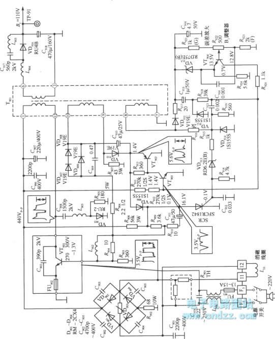
The control circuit is composed of the VT902~VT904. When the power supply is working, the induced voltage of the transformer T901's sampling windings ⑦~⑧ is rectified by the diode VD911 to supply to the error amplifier for the sampling amplification. The error voltage outputs from the collector electrode to the base electrode of VT903 to control the VT903's bias voltage. And the output pulse of the ⑦ ~ ⑧ end-windings is differentiated by the R919 and C913 to add to the base electrode of VT903. The two signals is superimposed to control the conduction and cut-off of VT902 and VT903. When the two tubes is cut-off, the rectangular pulse voltage of the feedback winding ⑨~⑩ ports is rectified by VD901 to establish the composite voltage on the capacitor C910, so the VD910 is anti-bias cut-off, the VT901 conducts.
Reprinted Url Of This Article:
http://www.seekic.com/circuit_diagram/Power_Supply_Circuit/Width_modulation_frequency_modulation_hybrid_type_switching_power_supply_2.html
Print this Page | Comments | Reading(3)

Article Categories
power supply circuit
Amplifier Circuit
Basic Circuit
LED and Light Circuit
Sensor Circuit
Signal Processing
Electrical Equipment Circuit
Control Circuit
Remote Control Circuit
A/D-D/A Converter Circuit
Audio Circuit
Measuring and Test Circuit
Communication Circuit
Computer-Related Circuit
555 Circuit
Automotive Circuit
Repairing Circuit
Code: