power supply circuit
WIRELESS_DC_PROBE
Published:2009/7/17 1:55:00 Author:Jessie | From:SeekIC

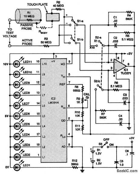
This probe for low voltages only (<100 V) uses the body to complete the dc circuit in a novel way. The schematic for the dc voltmeter is shown. Power for the circuit is provided by two 1.5-V N-type cells, B1 and B2, which are wired in series. For the circuit to work, it must be completed or closed. That is accomplished when the passive probe is held in one hand and the active probe is held in the other and the points of the two probes are placed across two points in a circuit under test. The resistor labeled Rbody is simply the resistance of the user's body. For Rbody to be swamped out, or kept from interfering with the reading, extremely high input-circuit impedances are used in the circuit. All of the people tested by the author for this project indicated a body resistance from hand to hand in the range of 200,000 to 500,000 Ω. Therefore, an input impedance of 50 MΩ, resistor R3, was added. That also provided an adequate safety isolation feature. The reduction of RFI and 60-Hz pickup is accomplished by the use of a symmetrical difference amplifier (IC1) at the input; the inherent common-mode rejection takes care of most the ac-related problems. The amplifier used for IC1 is a TLC271 CMOS op amp. Switch S1 is used to select polarity. Note that 50 MΩ of resistance are present at both of IC1's differential inputs (R3 at one input and the combined series resistance of R1 and R2 at the other). The user is placed in series with the 100-MΩ loop containing a 10-MΩ resistor (R1) as the protective device in the passive-probe section. Capacitors C1 to C4 provide additional filtering of residual ac noise and allow IC2, an LM3914 bar-graph display driver, to step up sequentially. Switch S2 selects between two selectable input ranges: XI, where each step equals 1 V, and X10, where each step equals 10 V. The display is made up of LED1 to LED11; LED2 through LED11 indicate the individual steps. LED1, the 0-V indicator, is also the power-on indicator.
Reprinted Url Of This Article:
http://www.seekic.com/circuit_diagram/Power_Supply_Circuit/WIRELESS_DC_PROBE.html
Print this Page | Comments | Reading(3)

Article Categories
power supply circuit
Amplifier Circuit
Basic Circuit
LED and Light Circuit
Sensor Circuit
Signal Processing
Electrical Equipment Circuit
Control Circuit
Remote Control Circuit
A/D-D/A Converter Circuit
Audio Circuit
Measuring and Test Circuit
Communication Circuit
Computer-Related Circuit
555 Circuit
Automotive Circuit
Repairing Circuit
Code: