power supply circuit
VOLTAGE_REGULATOR_SINKS_AND_SOURCES
Published:2009/7/16 21:21:00 Author:Jessie | From:SeekIC
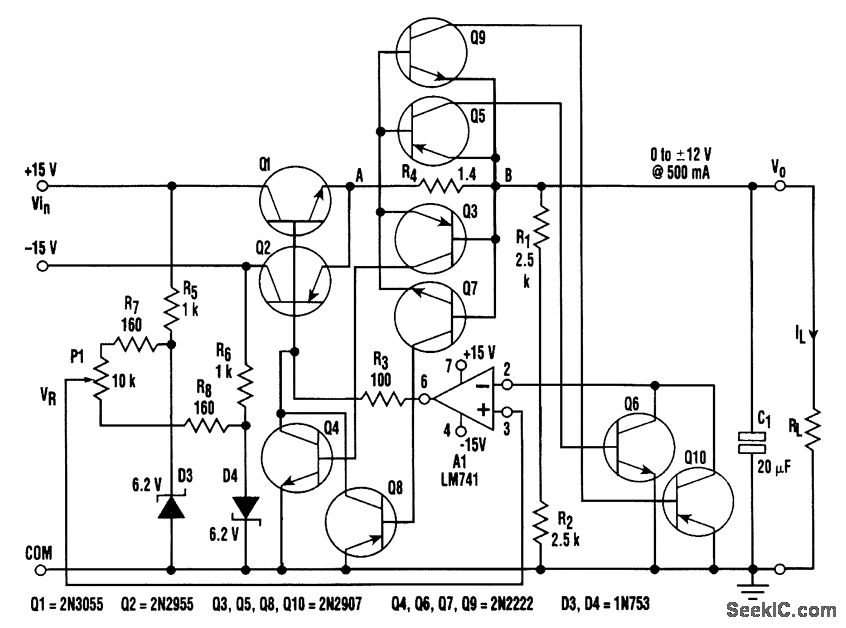
It is possible to build a circuit that provides a variable output from -12 to +12 V (passing smoothly through 0 V) that can source or sink at any voltage. The basic regulator consists of an op amp (A1), series pass transistors Q1 and Q2, a reference voltage from Pl, and a voltage divider (R1 and R2). The rest of the elements provide short-circuit protection for the regulator. The reference voltage is generated by zener diodes D3 and D4. With a 10-turn potentiometer (P1), the reference voltage (VR) for the of amp can be varied from -6 to +6 V. The output voltage is given by VO = VR (1 + R1/R2) Because R1 = R2, the output can be varied from 0 to ±12 V. When VO is positive and the regulator is sourcing current (IL positive), the base of Q1 is at VO+ 0.7m and Q1 is conducting. When VO is positive and RL is terminated in a supply voltage higher than VO, the regulator is forced to sink current (IL negative). At this time, Q2 conducts and sinks the current, and A1 maintains the base of Q2 at VO- 0.7. Similar arguments apply when the output voltage is negative. C1, a nonpolarized electrolytic capacitor, prevents oscillations. R4 is a current-sensing resistor for short-circuit protection and limits the output current to 55 mA. For a positive VO, if IL is positive (sourcing) and reaches 500 mA, the voltage drop VAB across R4 approaches 0.7 V and forward-biases the E-B junction of Q3. Q3 conducts and drives the base of Q4. Because Q4 goes into saturation as a result of the drop across R3, it clamps the base voltage of Q1 to ground and the output voltage drops, limiting the current in Q1 to 500 mA. Similarly, under a positive VO, if IL is negative (sinking) and reaches 500 mA, VAB across R4 approaches -0.7 V and forward-biases the E-B junction of Q5. Q5 drives Q6 into saturation, and the inverting input of the op amp is clamped to ground. Because the noninverting input is held at VR (which is still positive), the output starts climbing toward +15 V. This prevents Q2 from sinking more current than 500 mA. Under a negative VO, with IL negative, Q7 and Q8 provide short-circuit protection, With VO negative and positive, Q9 and Q10 provide short-circuit protection.
Reprinted Url Of This Article:
http://www.seekic.com/circuit_diagram/Power_Supply_Circuit/VOLTAGE_REGULATOR_SINKS_AND_SOURCES.html
Print this Page | Comments | Reading(3)

Article Categories
power supply circuit
Amplifier Circuit
Basic Circuit
LED and Light Circuit
Sensor Circuit
Signal Processing
Electrical Equipment Circuit
Control Circuit
Remote Control Circuit
A/D-D/A Converter Circuit
Audio Circuit
Measuring and Test Circuit
Communication Circuit
Computer-Related Circuit
555 Circuit
Automotive Circuit
Repairing Circuit
Code: