power supply circuit
Ultra_linear_V_F_converter
Published:2009/7/23 23:34:00 Author:Jessie | From:SeekIC

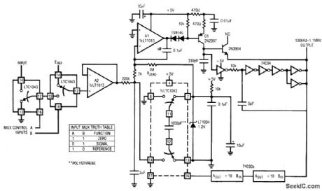
Fig. 12-10 Although this circuit can be used in a stand-alone mode, it is specifically intended for processor-driven applications, which require 17-bit accuracy, such as weighing scales. The circuit has a resolution of 1 ppm, with linearity inside 7 ppm (0.0007%). When combined with a processor-driven gain/zero calibration loop, the circuit has negligible zero and gain drift. A single 5-V supply is used to minimize interface problems. For processor operation, the input multiplexer (LTC1043) and RZERO (1 MΩ) must be added. With the multiplexer set to the ZERO function (see truth table) the A1 input is grounded, and the 200-kΩ.resistor receives no drive. However, At receives bias via RZERO and the circuit oscillates around 100 kHz. After reading this frequency, the processor shifts the multiplexer to the SIGNAL function, where the A2 output is a buffered version of the signal input. The circuit output frequency is now determined by this input, and the current through RZERO. Typical output range from 100 kHz to 1 MHz. Linear Technology. Linear Applications Handbook 1990 AN14-7.
Reprinted Url Of This Article:
http://www.seekic.com/circuit_diagram/Power_Supply_Circuit/Ultra_linear_V_F_converter.html
Print this Page | Comments | Reading(3)

Article Categories
power supply circuit
Amplifier Circuit
Basic Circuit
LED and Light Circuit
Sensor Circuit
Signal Processing
Electrical Equipment Circuit
Control Circuit
Remote Control Circuit
A/D-D/A Converter Circuit
Audio Circuit
Measuring and Test Circuit
Communication Circuit
Computer-Related Circuit
555 Circuit
Automotive Circuit
Repairing Circuit
Code: