power supply circuit
The 3-terminal voltage stabilizer circuit
Published:2011/7/24 7:49:00 Author:Seven | Keyword: 3-terminal, voltage stabilizer | From:SeekIC
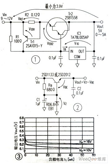
In the figure, resistor R1 provides bias current for the 3-terminal voltage stabilizer, and the need of R1<Veb2/Ib(max) must be met, if R1 is too high, the need in the above formula can't be met, the 3-terminal bias current is provided by base electricity of triode Tr2, and the output voltage is out of control.In figure 1, the output current of 0~5V is almost provided by Tr2, the power of Tr2 is large, so a radiator is needed.
A regulator diode can also form a simple regulator circuit, but the output current is only 10mA or so.
Reprinted Url Of This Article:
http://www.seekic.com/circuit_diagram/Power_Supply_Circuit/The_3_terminal_voltage_stabilizer_circuit.html
Print this Page | Comments | Reading(3)

Article Categories
power supply circuit
Amplifier Circuit
Basic Circuit
LED and Light Circuit
Sensor Circuit
Signal Processing
Electrical Equipment Circuit
Control Circuit
Remote Control Circuit
A/D-D/A Converter Circuit
Audio Circuit
Measuring and Test Circuit
Communication Circuit
Computer-Related Circuit
555 Circuit
Automotive Circuit
Repairing Circuit
Code: