power supply circuit
Switch type voltage stabilization nickel cadmium battery charger circuit
Published:2011/7/15 1:38:00 Author:TaoXi | Keyword: Switch type, voltage stabilization, nickel cadmium battery, charger circuit | From:SeekIC
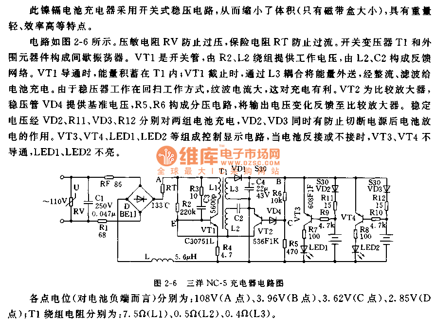
The circuit is as shown in the figure 2-6. The voltage dependent resistor RV prevents the overvoltage, the insurance resistance RT prevents the overcurrent. The blocking oscillator is composed of the switching transformer T1 and the external components. VT1 is the switching tube, the R2 and L2 windings supply the operating voltage to it, the feedback network composed of the L2 and C2. When the VT1 is conducting, the energy stores in T1; when VT1 is cutting off, the circuit outputs the energy through the L3 coupling, this energy is rectified and filted to charge the battery. Because the voltage stabilizer is working in the flyback mode, the ripple current is large, this is good for the charging. VT2 is the comparison amplifier, the voltage-regulator tube VD4 supplies the reference voltage, the voltage division circuit is composed of R5 and R6.
Reprinted Url Of This Article:
http://www.seekic.com/circuit_diagram/Power_Supply_Circuit/Switch_type_voltage_stabilization_nickel_cadmium_battery_charger_circuit.html
Print this Page | Comments | Reading(3)

Article Categories
power supply circuit
Amplifier Circuit
Basic Circuit
LED and Light Circuit
Sensor Circuit
Signal Processing
Electrical Equipment Circuit
Control Circuit
Remote Control Circuit
A/D-D/A Converter Circuit
Audio Circuit
Measuring and Test Circuit
Communication Circuit
Computer-Related Circuit
555 Circuit
Automotive Circuit
Repairing Circuit
Code: