power supply circuit
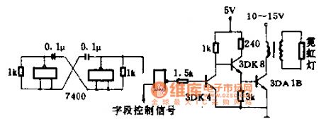
Strobe lights drive circuit diagram
Published:2014/3/3 20:13:00 Author: | Keyword: Strobe lights drive circuit diagram, | From:SeekIC

When the field control signal for low electricity at ordinary times, with the door closed, no signal output, this period is not bright neon lights.
1.5 K Ω for current-limiting resistance, protection, 3 dk4 value of B is good with 40-100, 3 dk4 B value in more than 40. Change 3 dk4 collector resistance, can change the current 3 dk4, to control the brightness of the light.
Magnetic core of pulse transformer with E12 at 11:45 type MXQ2000, primary 45 turns, wire diameter 0.51 mm enameled wire winding, the secondary use 0.21 mm high strength enamelled wire around 1500 turns.
Reprinted Url Of This Article:
http://www.seekic.com/circuit_diagram/Power_Supply_Circuit/Strobe_lights_drive_circuit_diagram.html
Print this Page | Comments | Reading(3)

Article Categories
power supply circuit
Amplifier Circuit
Basic Circuit
LED and Light Circuit
Sensor Circuit
Signal Processing
Electrical Equipment Circuit
Control Circuit
Remote Control Circuit
A/D-D/A Converter Circuit
Audio Circuit
Measuring and Test Circuit
Communication Circuit
Computer-Related Circuit
555 Circuit
Automotive Circuit
Repairing Circuit
Code: