power supply circuit
Step_up_voltage_regulator_with_voltage_dependent_oscillator
Published:2009/7/23 22:37:00 Author:Jessie | From:SeekIC

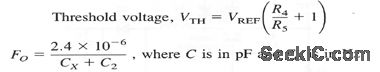
The circuit of Fig. 4-9 offers a compromise between load-current capability and output ripple (increased load current typically causes increased ripple). Component values are tailored to circuit requirements, as described for Fig.4-2, except as follows:
Typical component values are: R2= 330 kΩ, Rs=150 kΩ, Cx 100 pF, C2=100 pF. With these values, VTH is 4-1 V and Fo= 24 kHz. If the IC oscillator appears to be destabilized, or if there is excessive low-frequency ripple, look for stray capacitance at pin 7. Also, try a 100-pF to 10-nF capacitor in parallel with R2.
Reprinted Url Of This Article:
http://www.seekic.com/circuit_diagram/Power_Supply_Circuit/Step_up_voltage_regulator_with_voltage_dependent_oscillator.html
Print this Page | Comments | Reading(3)

Article Categories
power supply circuit
Amplifier Circuit
Basic Circuit
LED and Light Circuit
Sensor Circuit
Signal Processing
Electrical Equipment Circuit
Control Circuit
Remote Control Circuit
A/D-D/A Converter Circuit
Audio Circuit
Measuring and Test Circuit
Communication Circuit
Computer-Related Circuit
555 Circuit
Automotive Circuit
Repairing Circuit
Code: