power supply circuit
Sine_wave_output_V_F_converter
Published:2009/7/23 23:38:00 Author:Jessie | From:SeekIC

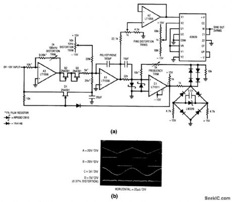
Fig. 12-12 Most of the V/F converters in this chapter produce pulse or square-wave outputs. Many applications (such as audio, filter, or automatic-equipment testing) require a sine-wave output, such as is produced by this circuit. The sine waves from this circuit span a range from 1 Hz to 100 kHz (100 dB or X5 decades) for a 0- to 10-V input, with 0.1% frequency linearity and 0.2% distortion. Drift is 150 ppm/℃ and zero-point drift is 0. 1 Hz/℃. To trim, apply 10.00 V and adjust the 2-kΩ 100-kHz distortion trim for a symmetrical triangle output at Al. Next, apply 100μV and adjust the 50-kΩ 10-Hz distortion trim for triangle symmetry. Then, apply 10.00 V again and adjust the 5-kΩ frequency trim for a 100.00-kHz output. Finally, adjust both 1-kΩ fine distortion trim potentiometers for minimum distortion of the sine-wave output (trace D of Fig. 12-12B). Slight readjustment of the other trim controls might be required to get the lowest possible distortion.
Reprinted Url Of This Article:
http://www.seekic.com/circuit_diagram/Power_Supply_Circuit/Sine_wave_output_V_F_converter.html
Print this Page | Comments | Reading(3)

Article Categories
power supply circuit
Amplifier Circuit
Basic Circuit
LED and Light Circuit
Sensor Circuit
Signal Processing
Electrical Equipment Circuit
Control Circuit
Remote Control Circuit
A/D-D/A Converter Circuit
Audio Circuit
Measuring and Test Circuit
Communication Circuit
Computer-Related Circuit
555 Circuit
Automotive Circuit
Repairing Circuit
Code: