power supply circuit
Several commonly used backup power supply circuit diagram
Published:2014/3/27 21:20:00 Author:lynne | Keyword: Several commonly used backup power supply circuit diagram, MC34164, LM2931T, ICL7673, MAX610, LM2935 | From:SeekIC

Here are a few dedicated uninterruptible power supply circuit, especially for low-power or batteries places. Can be used as a backup power source other low-voltage power circuit memory, microprocessors, CMOS circuits, timer and calendar clock circuit.
Self-based backup regulator
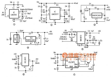
LM2935 is a low drop voltage regulator, in addition to a +5 V/750mA regulated output, the internal device also has a low quiescent backup regulator, its normal output is +5 V/10mA, Figure 1 shows a typical wiring LM2935 Figure. Backup function mainly regulator in the line when subjected to transient shocks (such as line input suddenly reaches 60V voltage exceeds the maximum input voltage transient limit), 750mA regulator output will automatically shut down to protect the internal circuitry and load, but still normal backup regulator output, as long as the reset level and ultra-low input voltage does not occur simultaneously, it can make a backup storage without data loss of normal power supply.
Power failure backup regulator circuit
Although low dropout regulator LM2931T just a battery regulator, using it as a power failure backup is very convenient. The circuit in Figure 2 when the normal power supply, input output directly through D3, D1 and R1 also by Ec backup battery trickle charge, LM2931T is high and 2 feet off the output; When the line when the input power failure, LM2931T 2 feet will be low, the output power to the load through D4 continued regulation. Backup circuit can accommodate a wide range of voltages, power regulator RP obtain suitable output circuit for the isolation diodes D1-D4, the best selection of low drop Schottky diode.
Backup power boost switch IC
RH5RCXXX series circuit is a three-terminal regulator IC CMOS switch, low current consumption of only 7.5uA. As long as the input voltage is greater than 0.9V, the boost switch output can be achieved, the conversion efficiency is generally above 80%. The circuit in Figure 3 constitutes a use RH5RCXX clamp boost backup power. The main power supply circuit E1, E2 as an auxiliary power when the main power output strong, diode D2 deadline, RH5RCXX boost circuit does not work; When the main power is turned down to D2, E2 will D1 auxiliary power off switch boost Backup power output circuit. Figure 4 is a power-saving backup power circuit. At higher battery voltage, output voltage detector 1 foot MC34164 blocking, V cutoff, power Ec directly through L, D1 output; supply Ec voltage drop is detected when IC1 effective, a pin output low, the end of the suction current of about 6mA, it was R so that V conduction, allowing the boost switch circuit, the battery Ec may continue to be used.
Transformerless power backup
With MAX's electricity converter MAX610 can constitute a +5 V uninterruptible power supplies, backup batteries use ultracapacitors. Under normal circumstances 2,8 feet rectified output of the IC through R3 backup battery trickle charge current is selected as the best one-tenth or less of battery capacity. When power cut, D conduction, so Ec by internal series regulator IC output freewheeling, the maximum output current up to 150mA, to ensure that the load is not power-down operation. It is noteworthy that the best choice of diode Schottky diode D, such as D83004, etc., buck capacitor C2 should have a withstand voltage of 450V or more, when the electricity is when 220V/50Hz, R1 take 100 ohms; When the mains voltage is When 110V/60Hz, R1 taken 47 ohm.
ASIC backup power
ICL7673 is a monolithic CMOS ASIC-based backup power can achieve output 2.5-15V input voltage range of backup power, then the normal power supply pin Vp, Vs take a backup power supply, power supply was normal Pbar bottom level, and Sbar blocking ; when energized,, Pbar blocked, and Sbar bottom level output; supply of +5 V when the output current is 38mA, when the power supply 3V, the output current is 30mA, Sbar and Pbar end load capacity of about 50mA. Small power backup power supply 6 is constituted by the ICL7673, spare battery with 3.6V lithium battery or super capacitor bank. When normal power supply, battery trickle charge to get. +5 V power failure, +3.6 V output will freewheeling diode D prevents backflow backup battery power is consumed in the normal end; To accommodate large load backup ICL7673, and Figure 7 pipe expansion flow output by PNP, V1 under normal circumstances lead Tong, V2 at the time of the backup power supply is turned on.
Several commonly used backup power supply circuit shown in Figure
Reprinted Url Of This Article:
http://www.seekic.com/circuit_diagram/Power_Supply_Circuit/Several_commonly_used_backup_power_supply_circuit_diagram.html
Print this Page | Comments | Reading(3)

Article Categories
power supply circuit
Amplifier Circuit
Basic Circuit
LED and Light Circuit
Sensor Circuit
Signal Processing
Electrical Equipment Circuit
Control Circuit
Remote Control Circuit
A/D-D/A Converter Circuit
Audio Circuit
Measuring and Test Circuit
Communication Circuit
Computer-Related Circuit
555 Circuit
Automotive Circuit
Repairing Circuit
Code: