power supply circuit
STEP_UP_REGULATOR
Published:2009/7/16 20:46:00 Author:Jessie | From:SeekIC

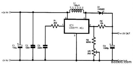
Refer to the figure for the circuit diagram of the step-up regulator. This circuit is based on an LM2577T-ADJ, which is designed to give a combination of high performance and simplicity. It can provide output currents of up to 3 A, and it has both overcurrent and thermal-protection circuits built in. It requires a minimum input potential of 3.5 V, and it shuts down automatically if the input voltage is inadequate. The maximum input voltage is 40 V. Capacitors C1 and C2 provide supply decoupling at the input, and C3 and resistor R1 provide frequency compensation. Inductor L1, diode D1, and an internal switching transistor of IC1 form a standard step-up output stage, with output smoothing provided by capacitor C4. Resistors R2 and R3 and preset VR1 form a potential divider that controls the output voltage. IC1 has an internal 1.2-V reference generator, and the voltage at pin 2 is, therefore, stabilized at this figure. With the specified values in the potential divider circuit, the output voltage range is around 9.5 to 25 V.
Reprinted Url Of This Article:
http://www.seekic.com/circuit_diagram/Power_Supply_Circuit/STEP_UP_REGULATOR.html
Print this Page | Comments | Reading(3)

Article Categories
power supply circuit
Amplifier Circuit
Basic Circuit
LED and Light Circuit
Sensor Circuit
Signal Processing
Electrical Equipment Circuit
Control Circuit
Remote Control Circuit
A/D-D/A Converter Circuit
Audio Circuit
Measuring and Test Circuit
Communication Circuit
Computer-Related Circuit
555 Circuit
Automotive Circuit
Repairing Circuit
Code: