power supply circuit
RC Buck power supply circuit
Published:2014/3/17 21:38:00 Author:lynne | Keyword: RC Buck power supply circuit, | From:SeekIC

Conventional methods AC power is converted to low voltage DC rectifier filter before using the step-down transformer, when restrictions on the size and cost factors, the most simple and practical method is to use capacitor step-down power supply.
First, the circuit schematic
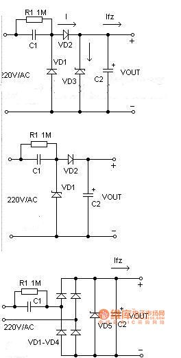
Simple basic buck power supply circuit capacitance in Fig, C1 is a step-down capacitor, D2 for the half-wave rectifier diode, D1 in the negative half cycle of the mains to provide a discharge circuit C1, D3 is a Zener diode, R1 is power off After the charge C1 bleeder resistor. Is often used in practical applications of the circuit shown in Figure 2. When the need to provide a larger load current, the bridge rectifier circuit can be used as shown in Figure 3.
Unregulated rectified DC voltage is generally higher than 30 volts, and will vary with changes in load current large fluctuations occur, it is because a lot of the reason of such power due to internal resistance, it is not suitable for high current power supply applications.
Conventional methods AC power is converted to low voltage DC rectifier filter before using the step-down transformer, when restrictions on the size and cost factors, the most simple and practical method is to use capacitor step-down power supply.
First, the circuit schematic
Simple basic buck power supply circuit capacitance in Figure 1, C1 is a step-down capacitor, D2 for the half-wave rectifier diode, D1 in the negative half cycle of the mains to provide a discharge circuit C1, D3 is a Zener diode, R1 is off C1 charge after power bleeder resistors. Is often used in practical applications of the circuit shown in Figure 2. When the need to provide a larger load current, the bridge rectifier circuit can be used.
Unregulated rectified DC voltage is generally higher than 30 volts, and will vary with changes in load current large fluctuations occur, it is because a lot of the reason of such power due to internal resistance, it is not suitable for high current power supply applications.
Second, the device selection
1 circuit design, the exact value should be measured load current, and then select the reference sample capacity buck capacitor. Because the capacitor C1 through the buck to the load current Io, flowing C1 actually charge and discharge current Ic. C1 greater capacity, the smaller the capacitive reactance Xc, then flows through C1 charge and discharge current increases. When the load current Io is less than C1 charge and discharge current, the excess current will flow through the regulator, if the regulator is less than the maximum allowable current Idmax Ic-Io when the regulator could easily lead to burnout.
(2) To ensure reliable operation of C1, the pressure should be chosen to be greater than twice the supply voltage.
3 bleeder resistor R1 must be selected to ensure that within the required time exhausting the charge on C1.
Third, the design example
Known C1 is 0.33μF, AC input 220V/50Hz, seeking circuit can supply a maximum current load. C1 reactance Xc in the circuit is:
Xc = 1 / (2 πf C) = 1 / (2 * 3.14 * 50 * 0.33 * 10-6) = 9.65K
Flows through the capacitor C1 of the charging current (Ic) is:
Ic = U / Xc = 220 / 9.65 = 22mA.
Capacitor C1 is often the relationship between blood pressure and the load current Io capacitance C can be approximated that: C = 14.5 I, where C is the capacity of the unit is μF, Io unit is A. Capacitor Buck is a non-isolated power supply, pay special attention to the application of isolation, to prevent electric shock.
RC Buck power supply circuit shown in Fig. :
Reprinted Url Of This Article:
http://www.seekic.com/circuit_diagram/Power_Supply_Circuit/RC_Buck_power_supply_circuit.html
Print this Page | Comments | Reading(3)

Article Categories
power supply circuit
Amplifier Circuit
Basic Circuit
LED and Light Circuit
Sensor Circuit
Signal Processing
Electrical Equipment Circuit
Control Circuit
Remote Control Circuit
A/D-D/A Converter Circuit
Audio Circuit
Measuring and Test Circuit
Communication Circuit
Computer-Related Circuit
555 Circuit
Automotive Circuit
Repairing Circuit
Code: