Position: Home > Circuit Diagram > power supply circuit > Quartz_stabilized_V_F_converter_external_clock
power supply circuit
Quartz_stabilized_V_F_converter_external_clock
Published:2009/7/23 23:23:00 Author:Jessie | From:SeekIC

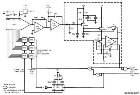
Fig. 12-6 This circuit requires an external4-kHz clock, but it provides very high linearity (typically 0.025%, limited by the 6012 DAC). Range is 1 Hz to 30 MHz, with a typical full-scale drift of 50 ppm/℃, and a zero-point error of about 0.3μV/℃. The circuit is trimmed at the 30-MHz end with the 5000-0 feedback resistor of A1A. Linear Technology linear Applications Handbook, 1990 p AN13-11.
Reprinted Url Of This Article:
http://www.seekic.com/circuit_diagram/Power_Supply_Circuit/Quartz_stabilized_V_F_converter_external_clock.html
Print this Page | Comments | Reading(3)

Article Categories
power supply circuit
Amplifier Circuit
Basic Circuit
LED and Light Circuit
Sensor Circuit
Signal Processing
Electrical Equipment Circuit
Control Circuit
Remote Control Circuit
A/D-D/A Converter Circuit
Audio Circuit
Measuring and Test Circuit
Communication Circuit
Computer-Related Circuit
555 Circuit
Automotive Circuit
Repairing Circuit
Code: