power supply circuit
Programmable_lozo_dropout_voltage_regulator
Published:2009/7/24 3:46:00 Author:Jessie | From:SeekIC
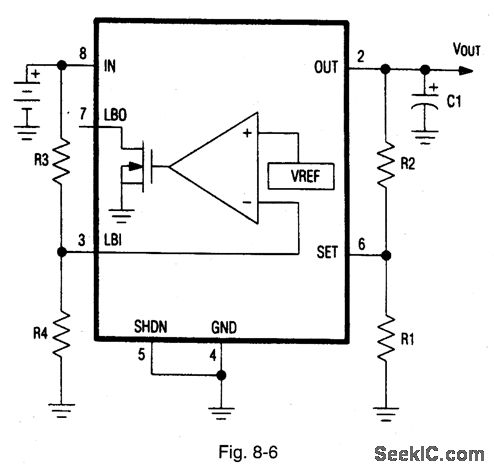
Figure 8-6 shows the MAX667 connected to provide a programmable output from +1.3 V to +16 V, with a low-battery function. Let R1 be 1 MΩ, and select R2 for a desired output using: R2= R1× (VOUT/VSET-1), where VSET= 1.225 V. Let R4 be 2.4 MΩ, and select R3 for a desired threshold of the low-battery detector using: R3=R4 ×(VBATT/VLBI-1). where VBATT is the desired threshold of the low-battery detector, and R3/R4 are the LBI input divider resistors. If VOUT is 5 V, a 5.5-V low-battery threshold can be set using 8.2 MΩ for R3 and 2.4 MΩ for R4. MAXIM NEW RELEASES DATA BOOk, 1992, p 4-137.
Reprinted Url Of This Article:
http://www.seekic.com/circuit_diagram/Power_Supply_Circuit/Programmable_lozo_dropout_voltage_regulator.html
Print this Page | Comments | Reading(3)

Article Categories
power supply circuit
Amplifier Circuit
Basic Circuit
LED and Light Circuit
Sensor Circuit
Signal Processing
Electrical Equipment Circuit
Control Circuit
Remote Control Circuit
A/D-D/A Converter Circuit
Audio Circuit
Measuring and Test Circuit
Communication Circuit
Computer-Related Circuit
555 Circuit
Automotive Circuit
Repairing Circuit
Code: