power supply circuit
Programmable_Zener_voltage_reference
Published:2009/7/24 20:07:00 Author:Jessie | From:SeekIC
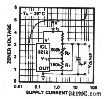

In this circuit, an ICL8212 stimulates a Zener diode by connecting the output terminal (pin 4) to the VZ output, and using a resistor network connected at the VTH terminal (pin 3) to program the Zener voltage. Power (V+) is applied to pin 8, with pin 5 connected to ground. The zener voltage is calculated by:
Because there is no internal compensation, the 5-μF capacitor is required across the output to prevent oscillation. Zener voltages from 2 to 30 V can be programmed. Typical impedance values between 300 μA and 25 mA range from 4 to 7Ω. The Zener knee is sharper and occurs at a significantly lower current than similar devices.
Reprinted Url Of This Article:
http://www.seekic.com/circuit_diagram/Power_Supply_Circuit/Programmable_Zener_voltage_reference.html
Print this Page | Comments | Reading(3)

Article Categories
power supply circuit
Amplifier Circuit
Basic Circuit
LED and Light Circuit
Sensor Circuit
Signal Processing
Electrical Equipment Circuit
Control Circuit
Remote Control Circuit
A/D-D/A Converter Circuit
Audio Circuit
Measuring and Test Circuit
Communication Circuit
Computer-Related Circuit
555 Circuit
Automotive Circuit
Repairing Circuit
Code: