power supply circuit
Practical circuit of the half-bridge type switching voltage stabilization power supply
Published:2011/7/12 3:14:00 Author:TaoXi | Keyword: Practical circuit, half-bridge, switching, voltage stabilization, power supply | From:SeekIC
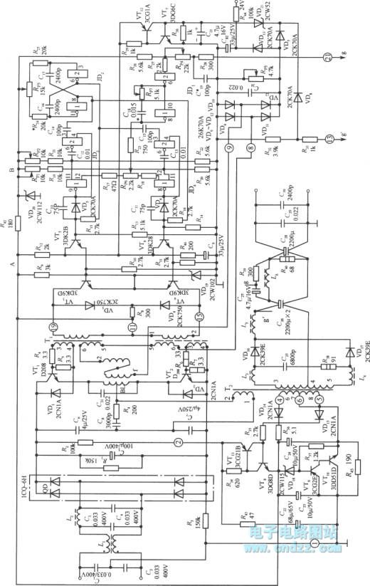
The practical circuit of the half-bridge type switching voltage stabilization power supply is as shown in the figure. The half-bridge type converter is composed of the VTl, VT2, T2, C6 and C7. The control signal is amplified by the VT3 and VT4, and it drives the switching tubes VT1, VT2 to alternately turn on and off through the transformer T1. The two ends of the T2's primary coil is connected with the midpoint of C6, C7 and the midpoint of VTl, VT2, so it can couple the power signal to the secondary stage of T2. And it outputs the stable DC through the VDl6, VDl7 full-wave rectification and the L6, C28 two-stage filtering.
The control circuit uses three dual NAND gate ICs as the main part. The JD2 is the timer, it produces the 20kHz square wave. The two monostable triggers are composed of the JD3 and JD4, and the two monostable triggers form the pulse width regulator.
Reprinted Url Of This Article:
http://www.seekic.com/circuit_diagram/Power_Supply_Circuit/Practical_circuit_of_the_half_bridge_type_switching_voltage_stabilization_power_supply.html
Print this Page | Comments | Reading(3)

Article Categories
power supply circuit
Amplifier Circuit
Basic Circuit
LED and Light Circuit
Sensor Circuit
Signal Processing
Electrical Equipment Circuit
Control Circuit
Remote Control Circuit
A/D-D/A Converter Circuit
Audio Circuit
Measuring and Test Circuit
Communication Circuit
Computer-Related Circuit
555 Circuit
Automotive Circuit
Repairing Circuit
Code: