power supply circuit
PUT_BATTERY_CHARGER
Published:2009/7/6 4:25:00 Author:May | From:SeekIC

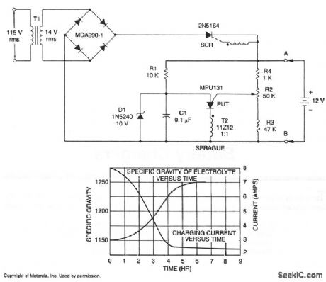
A short-circuit-proof battery charger will provide an average charging current of about 8 A to a 12-V lead/acid storage battery. The charger circuit has an additional advantage; it will not function nor will it be damaged by improperly connecting the battery to the circuit. With 115 V at the input, the circuit commences to function when the battery is properly attached. The battery provides the current to charge the timing capacitor C1 used in the PUT relaxation oscillator. When C1 charges to the peak point voltage of the PUT, the PUT fires turning the SCR on,which in turn applies charging current to the battery. As the battery charges, the battery voltage increases slightly which increases the peak point voltage of the PUT.This means that C1 has to charge to a slightly higher voltage to fire the PUT. The voltage on C1 increases until the zener voltage of Dl is reached, which clamps the voltage on C1, and thus prevents the PUT oscillator from oscillating and charging ceases. The maximum battery voltage is set by potentiometer R2 which sets the peak point firing voltage of the PUT. In the circuit shown, the charging voltage can be set from 10 V to 14 V-the lower limit being set by Dl and the upper limit by T1.
Reprinted Url Of This Article:
http://www.seekic.com/circuit_diagram/Power_Supply_Circuit/PUT_BATTERY_CHARGER.html
Print this Page | Comments | Reading(3)

Article Categories
power supply circuit
Amplifier Circuit
Basic Circuit
LED and Light Circuit
Sensor Circuit
Signal Processing
Electrical Equipment Circuit
Control Circuit
Remote Control Circuit
A/D-D/A Converter Circuit
Audio Circuit
Measuring and Test Circuit
Communication Circuit
Computer-Related Circuit
555 Circuit
Automotive Circuit
Repairing Circuit
Code: