power supply circuit
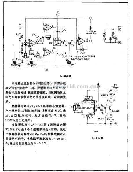
Opto-electrical range acquisition circuit
Published:2011/4/24 5:05:00 Author:Nicole | Keyword: opto-electrical range acquisition circuit | From:SeekIC

This circuit is composed of transmitter(a) and receiver(2), they are put side by side. Transmitter emits optical pulse, the light is reflected by the measured object and then received by the receiver. It has proportional relationship to the distance of measured object and the degree of received optical singal.
In transmitter circuit, IC14047 is monostable trigger, it produces 10kHz square wave, the frequency is decided by R1, C1, the duty ratio is 50%. By T1, T2, this square wave drives LD271 to emit optical pulse.
Reprinted Url Of This Article:
http://www.seekic.com/circuit_diagram/Power_Supply_Circuit/Opto_electrical_range_acquisition_circuit.html
Print this Page | Comments | Reading(3)

Article Categories
power supply circuit
Amplifier Circuit
Basic Circuit
LED and Light Circuit
Sensor Circuit
Signal Processing
Electrical Equipment Circuit
Control Circuit
Remote Control Circuit
A/D-D/A Converter Circuit
Audio Circuit
Measuring and Test Circuit
Communication Circuit
Computer-Related Circuit
555 Circuit
Automotive Circuit
Repairing Circuit
Code: