power supply circuit
Opto-electrical linear detection circuit
Published:2011/3/30 2:29:00 Author:Nicole | Keyword: linear detection circuit | From:SeekIC

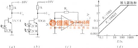
The figures (a), (b) are the light current amplification circuit which work in the linear region. The transistor in figure (a) must be germanium tube. Because the maximum open circuit voltage of photocell is only 0.6V, while the silicone tube turn on need 0.7V. When the output voltage produced by light is more than 0.3V, transistor 3AX4 starts to conduct, output voltage Usc begins to decrease from -10V. Due to the resistance of 3AX4 is lower, so it can obtain good linear output. The figure (b) adopts two photocells in series, transistor uses silicon tube. The circuit in figure (c) is connected with operational amplifier, the equivalent load resistance is zero, so the output voltage of operational amplifier is equal to the product of silicon photocell short-circuit current Isc and amplifier feedback resistor Rf, that is USc = IscRf, and the output has good linearity, as shown in (d).
Reprinted Url Of This Article:
http://www.seekic.com/circuit_diagram/Power_Supply_Circuit/Opto_electrical_linear_detection_circuit.html
Print this Page | Comments | Reading(3)

Article Categories
power supply circuit
Amplifier Circuit
Basic Circuit
LED and Light Circuit
Sensor Circuit
Signal Processing
Electrical Equipment Circuit
Control Circuit
Remote Control Circuit
A/D-D/A Converter Circuit
Audio Circuit
Measuring and Test Circuit
Communication Circuit
Computer-Related Circuit
555 Circuit
Automotive Circuit
Repairing Circuit
Code: