power supply circuit
Opto-electrical alarm circuit
Published:2011/4/24 5:20:00 Author:Nicole | Keyword: opto-electrical alarm circuit | From:SeekIC

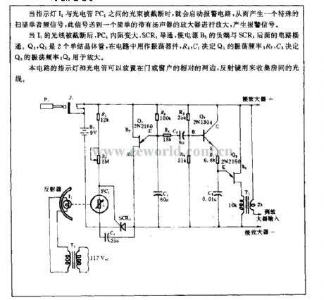
When the light beam between indicator light I1 and phototube PC1 is cut off, it will start alarm circuit, to produce a special scan single audio singal, this singal is sent to a simple amplifier with loudspeaker to amplify, then it will produce a alarm singal.
After the I1 light is cut off, PC1 resistance turns large, SCR1 turns on, the nagative terminal of power supply B1 is connected to the later SCR1 circuit. Q1, Q2 are two unijunction transistors, it is used as oscillation component, Q1's oscillation frequency is decided by R3, C1; Q3's oscillation frequency is decided by R7, C3; Q2 is used to amplify.
Reprinted Url Of This Article:
http://www.seekic.com/circuit_diagram/Power_Supply_Circuit/Opto_electrical_alarm_circuit.html
Print this Page | Comments | Reading(3)

Article Categories
power supply circuit
Amplifier Circuit
Basic Circuit
LED and Light Circuit
Sensor Circuit
Signal Processing
Electrical Equipment Circuit
Control Circuit
Remote Control Circuit
A/D-D/A Converter Circuit
Audio Circuit
Measuring and Test Circuit
Communication Circuit
Computer-Related Circuit
555 Circuit
Automotive Circuit
Repairing Circuit
Code: