power supply circuit
Opto-electrical adjustment circuit
Published:2011/4/22 21:36:00 Author:Nicole | Keyword: opto-electrical adjustment circuit | From:SeekIC

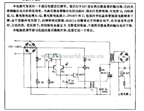
This circuit can be used to adjust a high voltage power supply. Indicator light #327 is connected to the output terminal of high voltage rectifier, its brightness changes in relation to output voltage. When the output voltage of high voltage rectifier is too high, the brightness of indicator light increases, the resistance of phototube Q3 reduces, Q1 collector current increases, Q2 collector current decreases, the frequency of unijunction transistor oscillation circuit composed of 2N4870 and C1 drops, limited by the frequency response of pulse transformer T1, MAC14 grid can not reach the trigger level, when the AC singal is zero passage, the light turns off automatically. The primary current of transformer T2 is reduced by R1 branch, then the output voltage of high voltage rectifier drops.
The feature of this circuit is to isolate the regulator from the dangerous high voltage.
Reprinted Url Of This Article:
http://www.seekic.com/circuit_diagram/Power_Supply_Circuit/Opto_electrical_adjustment_circuit.html
Print this Page | Comments | Reading(3)

Article Categories
power supply circuit
Amplifier Circuit
Basic Circuit
LED and Light Circuit
Sensor Circuit
Signal Processing
Electrical Equipment Circuit
Control Circuit
Remote Control Circuit
A/D-D/A Converter Circuit
Audio Circuit
Measuring and Test Circuit
Communication Circuit
Computer-Related Circuit
555 Circuit
Automotive Circuit
Repairing Circuit
Code: