power supply circuit
NEON_TUBE_HIGH_VOLTAGE_POWER_SUPPLY
Published:2009/7/16 21:58:00 Author:Jessie | From:SeekIC
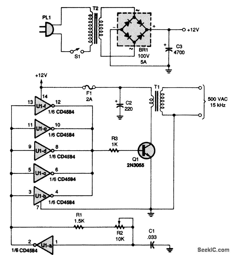
Power for the circuit is supplied by a step-down transformer (T2) and a full-wave bridge rectifier (BR1), which convert 117-Vac to 12-Vdc. Capacitor C3 acts as a filter. The heart of the circuit is a Schmitt-trigger hex inverter, U1. Capacitor C1, resistor R1, and potentiometer R2 are connected to one section of the inverter, U1-a, to form an oscillator that runs at approximately 15 kHz (because U1 is a Schmitt trigger, the output square wave is very clean). Adjusting R2 varies the frequency. The output of the oscillator is fed into the remaining five inverters (U1-b through U1-f), which are connected in parallel to create a buffer that is capable of increasing the drive current of the oscillator. The square-wave output is used to drive the switching transistor (Q1), which, in turn, switches the primary windings of the ferrite-core transformer (T1). Approximately 500-Vac at 15 kHz are output from the secondary of the transformer. T1 is made from a ferrite pot core. Wind 500 turns of #30-gauge wire for the secondary. Coat it with insulating varnish and add a layer of insulating tape, over which a 20-turn winding of #22 wire is wound to form the primary winding.
Reprinted Url Of This Article:
http://www.seekic.com/circuit_diagram/Power_Supply_Circuit/NEON_TUBE_HIGH_VOLTAGE_POWER_SUPPLY.html
Print this Page | Comments | Reading(3)

Article Categories
power supply circuit
Amplifier Circuit
Basic Circuit
LED and Light Circuit
Sensor Circuit
Signal Processing
Electrical Equipment Circuit
Control Circuit
Remote Control Circuit
A/D-D/A Converter Circuit
Audio Circuit
Measuring and Test Circuit
Communication Circuit
Computer-Related Circuit
555 Circuit
Automotive Circuit
Repairing Circuit
Code: