power supply circuit
Low Power 5V Switching Regulator
Published:2013/3/20 1:39:00 Author:Ecco | Keyword: Low Power, 5V , Switching Regulator | From:SeekIC

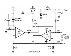
This simple switching regulator circuit have 5 V output, the input provide by a 9 V battery. Ithaving 80% efficiency and 50mA output capability.
How simple switching Regulator works:While Q1 is actually on, its collector voltage increases, delivering current through the inductor. The output voltage goes up, triggering A1′s(precision op amp LT1013) output to rise. Q1 cuts off as well as the output decays through the load.
The 100pF capacitor would ensure clean switching. The cycle repeats when the output falls low enough for A1 to turn on Transistor Q1. The 1µF capacitor ensures low battery impedance at high frequencies, preventing sag during switching.
Reprinted Url Of This Article:
http://www.seekic.com/circuit_diagram/Power_Supply_Circuit/Low_Power_5V_Switching_Regulator.html
Print this Page | Comments | Reading(3)

Article Categories
power supply circuit
Amplifier Circuit
Basic Circuit
LED and Light Circuit
Sensor Circuit
Signal Processing
Electrical Equipment Circuit
Control Circuit
Remote Control Circuit
A/D-D/A Converter Circuit
Audio Circuit
Measuring and Test Circuit
Communication Circuit
Computer-Related Circuit
555 Circuit
Automotive Circuit
Repairing Circuit
Code: