Position: Home > Circuit Diagram > power supply circuit > Intelligent charging typical circuit composed of ATC105 intelligent Ni-Cd battery charge control integrated circuit
power supply circuit
Intelligent charging typical circuit composed of ATC105 intelligent Ni-Cd battery charge control integrated circuit
Published:2011/4/18 4:40:00 Author:Nicole | Keyword: intelligent charging, Ni-Cd battery, charge control | From:SeekIC
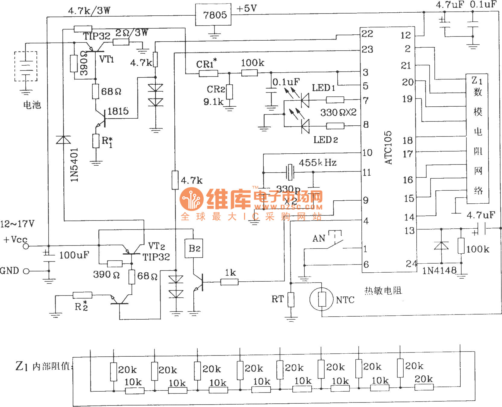
In this circuit, the best number of battery are 2~6. The battery testing input sampling resistance is CR1=4.3·(N-2)kΩ(N is the number of battery), if there are only two batteries, then CR1=0, it means this circuit at least needs two battery to charge in serie.
Reprinted Url Of This Article:
http://www.seekic.com/circuit_diagram/Power_Supply_Circuit/Intelligent_charging_typical_circuit_composed_of_ATC105_intelligent_Ni_Cd_battery_charge_control_integrated_circuit.html
Print this Page | Comments | Reading(3)

Article Categories
power supply circuit
Amplifier Circuit
Basic Circuit
LED and Light Circuit
Sensor Circuit
Signal Processing
Electrical Equipment Circuit
Control Circuit
Remote Control Circuit
A/D-D/A Converter Circuit
Audio Circuit
Measuring and Test Circuit
Communication Circuit
Computer-Related Circuit
555 Circuit
Automotive Circuit
Repairing Circuit
Code: