power supply circuit
IMPROVED_CLIPPING_CIRCUIT_DESIGN
Published:2009/7/16 21:58:00 Author:Jessie | From:SeekIC

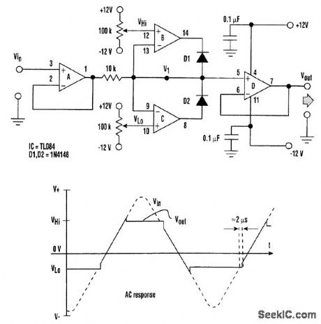
Op amps A and D form unity-gain buffer amplifiers. Op amps B and C compare the input voltage (Vin) with the reference voltages (VHi and VLo). These references set the high and low clipping levels of the circuit. When the input voltage lies in the range (VHi-VLo), the outputs of the comparators make both diodes (D1 and D2) reverse-biased. As a result, the circuit's output Vout follows the input voltage. When the input voltage exceeds the value VHi op amp B's output goes negative, forward-biasing D1 and thus reducing V1 the voltage at the invertinginput of op amp B. The circuit reaches an equilibrium condition at which Vout=V1=VHi Similarly, when the input voltage goes below the value VLo, op amp C's output goes positive, forward-biasing D2. This increases the voltage at V1, At the equilibrium condition, Vout=V1=VLo. The circuit's output continues to follow the input for about 2μs, even after the input voltage crosses the reference voltages, because of the slew rates of the op amps.The supplies (5V≤V+≤15V, -5V≥V-≥-15 V).
Reprinted Url Of This Article:
http://www.seekic.com/circuit_diagram/Power_Supply_Circuit/IMPROVED_CLIPPING_CIRCUIT_DESIGN.html
Print this Page | Comments | Reading(3)

Article Categories
power supply circuit
Amplifier Circuit
Basic Circuit
LED and Light Circuit
Sensor Circuit
Signal Processing
Electrical Equipment Circuit
Control Circuit
Remote Control Circuit
A/D-D/A Converter Circuit
Audio Circuit
Measuring and Test Circuit
Communication Circuit
Computer-Related Circuit
555 Circuit
Automotive Circuit
Repairing Circuit
Code: