power supply circuit
HIGH_VOLTAGE_PULSE_SUPPLY
Published:2009/7/16 21:02:00 Author:Jessie | From:SeekIC
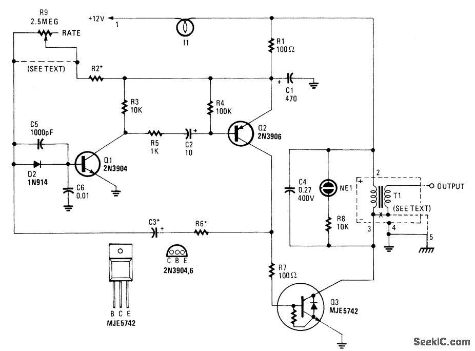
This high-voltage pulse supply will generate pulses up to 30 kV. Q1 and Q2 form a multivibrator in conjunction with peripheral components R1 through R6 and C1, C2, C3, C5, C6, and D2. R9 adjusts the pulse repetition rate. R2 should be selected to limit the maximum repetition rate to 20 Hz. I1 is a type 1156 lamp used as a current limiter. R9 can be left out and R2 selected to produce a fixed rate, if desired.Try about 1 MΩ as a start.Q3 serves as a power amplifier and switch to drive T1 (an automotive ignition coil). NE1 is used as a pulse indicator and indicates circuit operation. Because this circuit can develop up to 30 kV, suitable construction techniques and safety precautions should be observed.
Reprinted Url Of This Article:
http://www.seekic.com/circuit_diagram/Power_Supply_Circuit/HIGH_VOLTAGE_PULSE_SUPPLY.html
Print this Page | Comments | Reading(3)

Article Categories
power supply circuit
Amplifier Circuit
Basic Circuit
LED and Light Circuit
Sensor Circuit
Signal Processing
Electrical Equipment Circuit
Control Circuit
Remote Control Circuit
A/D-D/A Converter Circuit
Audio Circuit
Measuring and Test Circuit
Communication Circuit
Computer-Related Circuit
555 Circuit
Automotive Circuit
Repairing Circuit
Code: