power supply circuit
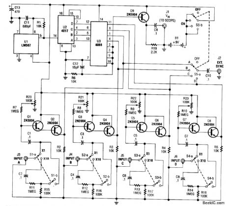
FOUR_TRACE_OSCILLOSCOPE_ADAPTER
Published:2009/7/10 1:59:00 Author:May | From:SeekIC

This simple adapter uses an oscillator (567) to drive a counter (U2) and switch (U3) that selects the output of one of four scope preamps (Q1/Q2 through Q7/Q8) and feeds it to buffer Q9 and output jack J1. J2 provides synch to the scope. R20 through R23 are posting controls for channels A through D (J3 through J6). SlA-B through S4A-B are switched attenuators, one for each channel. Switching rate is about 125 kHz. This circuit is useful for adding four-trace operation to inexpensive oscilloscopes. Signal levels of 0 to 20 V can be handled.
Reprinted Url Of This Article:
http://www.seekic.com/circuit_diagram/Power_Supply_Circuit/FOUR_TRACE_OSCILLOSCOPE_ADAPTER.html
Print this Page | Comments | Reading(3)

Article Categories
power supply circuit
Amplifier Circuit
Basic Circuit
LED and Light Circuit
Sensor Circuit
Signal Processing
Electrical Equipment Circuit
Control Circuit
Remote Control Circuit
A/D-D/A Converter Circuit
Audio Circuit
Measuring and Test Circuit
Communication Circuit
Computer-Related Circuit
555 Circuit
Automotive Circuit
Repairing Circuit
Code: