power supply circuit
FONT_face=VerdanaRSUB1_SUB_RSUB2_SUB_–_VSUB1_SUB_VSUB2_SUB_FONT_frequency_converter
Published:2009/7/23 23:44:00 Author:Jessie | From:SeekIC
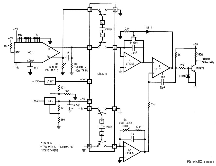
Fig, 12-16 This circuit produces an output frequency that is proportional to the ratio of voltages across two external resistors. The circuit has wide application in transducer signal-conditioning (chapter 14). Both R1 and R2 are ground-referred for noise considerations. In this particular circuit, R1 is a platinum resistance sensor and R2 is set at the R1 0℃ value. The circuit may be used with any resistive-based transducer. For negative TC devices, reverse the positions of R1 and R2. The grounded end of R2 allows fine trimming with decade boxes (if necessary to compensate for R1 tolerances at 0°) without excessive noise problems. The grounded side of R1 permits RI to be located at the end of a cable run (again without noise problems). The DAC serves as a simple source of two identical currents (The DAC MSB is set high, with all other bits low). With constant and equal currents, R1 and R2 produce a differential voltage, which is sampled by the LTC1043 switched-capacitor in the normal manner. To trim, place R1 in a 100℃ environment and adjust the full-scale trim for a 1-kHz output. Linear Technology. Linear Applications Handbook, 1990 p. AN14-17.
Reprinted Url Of This Article:
http://www.seekic.com/circuit_diagram/Power_Supply_Circuit/FONT_face=VerdanaRSUB1_SUB_RSUB2_SUB_–_VSUB1_SUB_VSUB2_SUB_FONT_frequency_converter.html
Print this Page | Comments | Reading(3)

Article Categories
power supply circuit
Amplifier Circuit
Basic Circuit
LED and Light Circuit
Sensor Circuit
Signal Processing
Electrical Equipment Circuit
Control Circuit
Remote Control Circuit
A/D-D/A Converter Circuit
Audio Circuit
Measuring and Test Circuit
Communication Circuit
Computer-Related Circuit
555 Circuit
Automotive Circuit
Repairing Circuit
Code: